

Activating hydroprocessing catalysts using carbon monoxide
a hydroprocessing catalyst and carbon monoxide technology, applied in the direction of catalyst regeneration/reactivation, physical/chemical process catalysts, metal/metal-oxides/metal-hydroxide catalysts, etc., can solve the problems of undesirable or desirable
- Summary
- Abstract
- Description
- Claims
- Application Information
AI Technical Summary
Problems solved by technology
Method used
Image

Examples
example 1
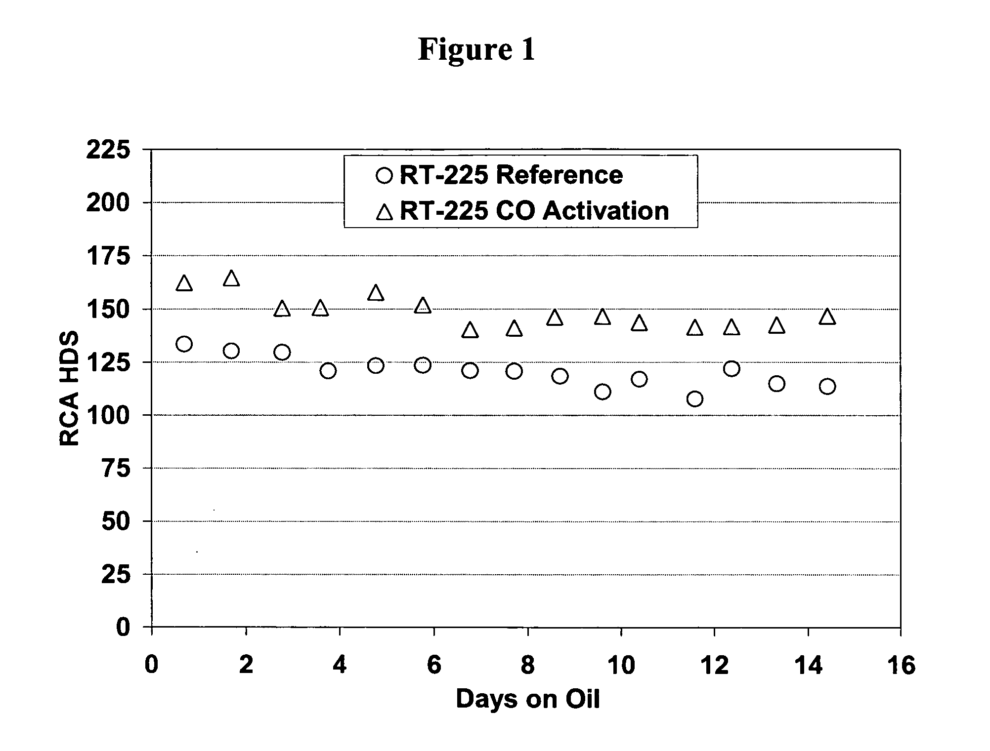
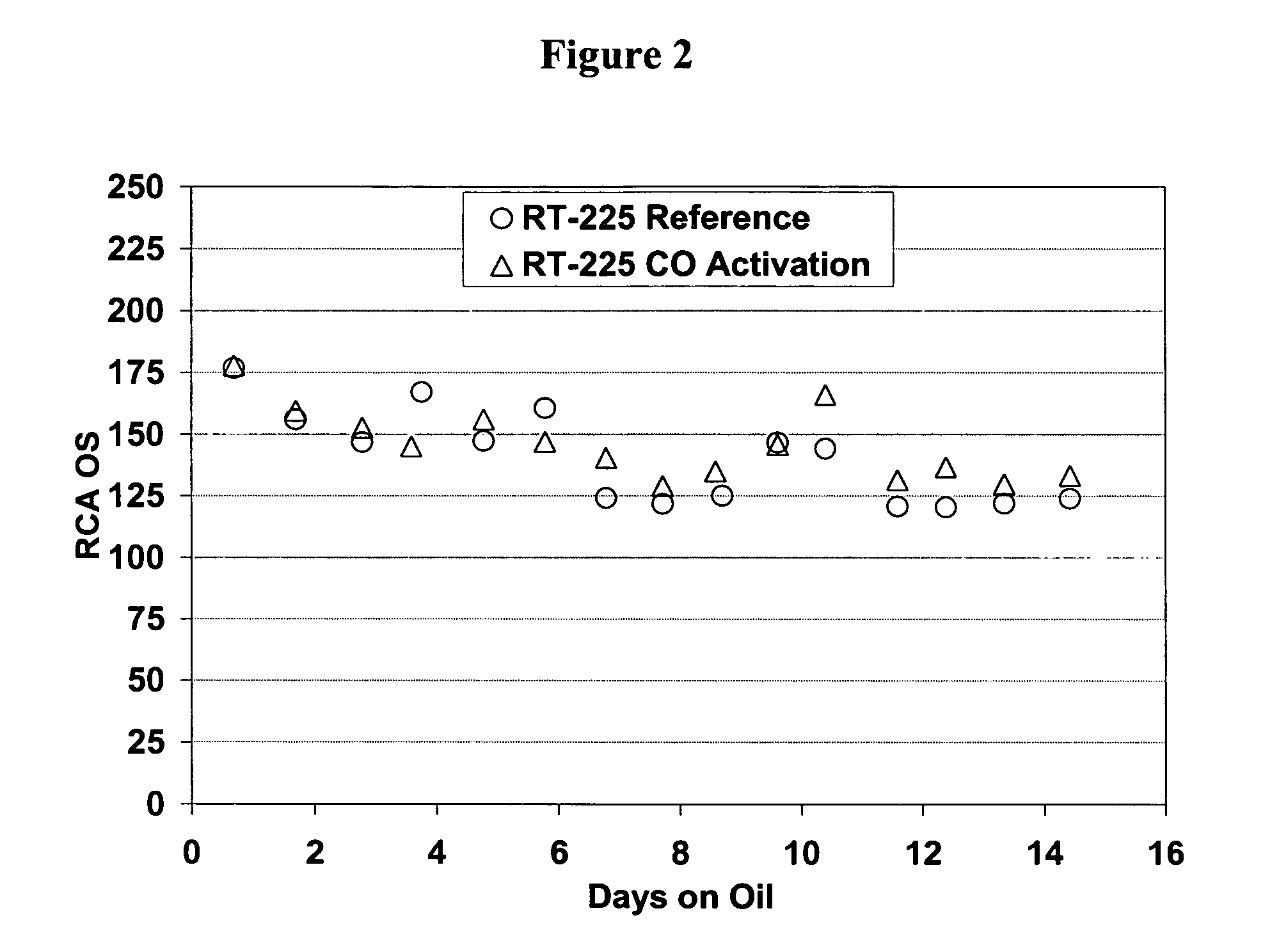
[0036] A commercially prepared sample of RT-225, commercially available from Albermarle, was used for this test. RT-225 was tested in a 1.3 mm asymmetric quadralobe form and is a CoMo on alumina catalyst with approximately 4.5 wt. % MoO3 and 1.2 wt. % CoO. Two naphtha pilot units were used for this test. Reactor 1 and Reactor 2 were used to test the effect of sulfiding with 10 vol. % hydrogen sulfide, 1000 vppm carbon monoxide and the balance hydrogen. Reactor 2 was used as a reference run using 10 vol. % hydrogen sulfide and 90 vol. % hydrogen during the sulfiding procedure. Both pilot units were loaded with 40 cubic centimeters of RT-225 and both used an intermediate cat naphtha (ICN) during the sulfiding procedure. Catalyst sulfiding was performed in-situ using the gas blends given above. The sulfiding was carried out for approximately 12 hours at holding temperatures of 204° C. and 343° C. with a reactor pressure of 305 psig. After sulfiding, the reactors were cooled to 274° C. ...
example 2
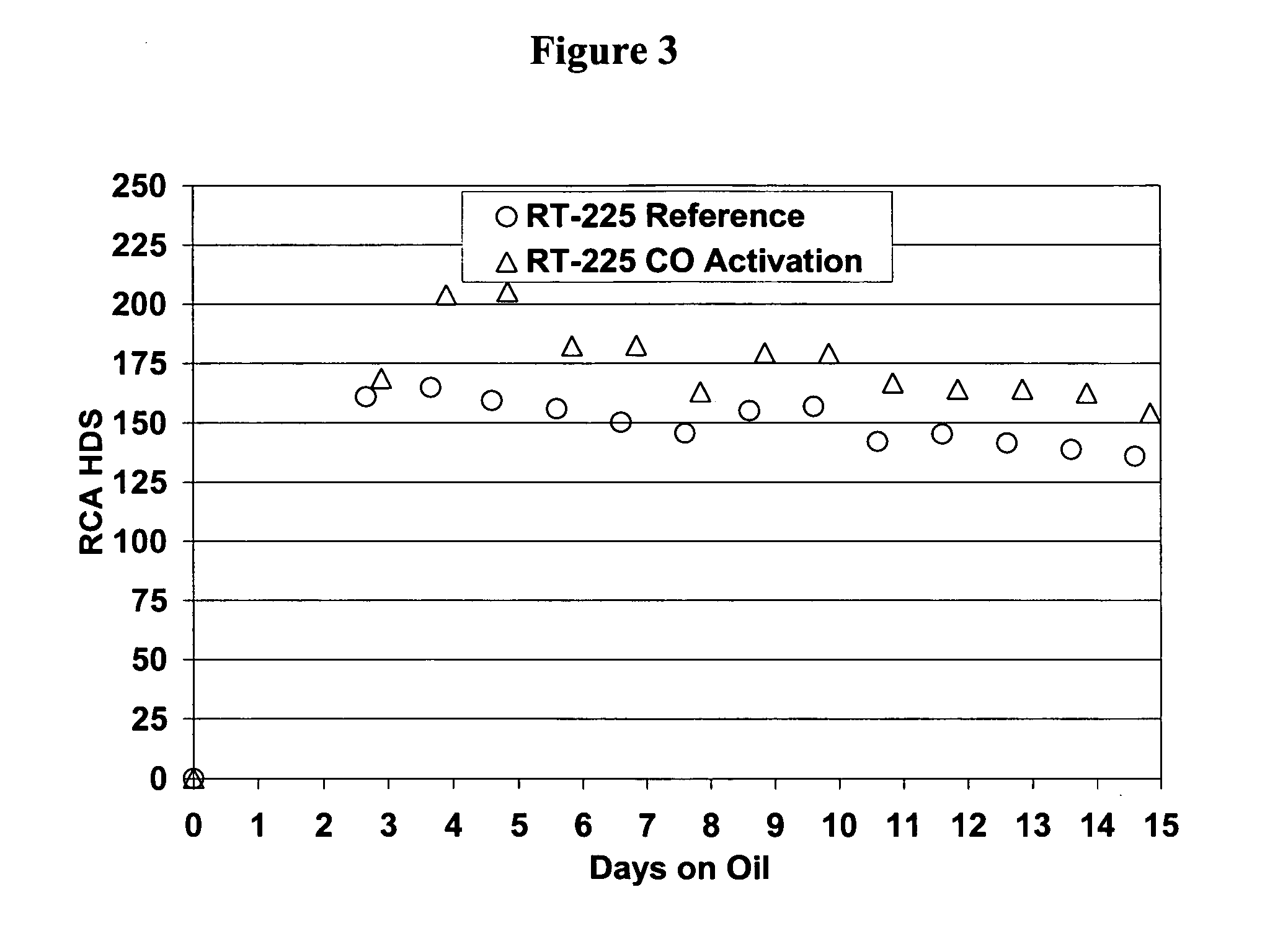
[0037] Commercially prepared samples of RT-225 were used for this test. RT-225 was tested in a 1.3 mm ASQ form and is a CoMo on alumina catalyst with approximately 4.5 wt. % MoO3 and 1.2 wt. % CoO. Three naphtha pilot units were used for this test. Reactor B was used to test the effect of sulfiding with 10 vol. % hydrogen sulfide, 1000 vppm carbon monoxide and the balance hydrogen with intermediate cat naphtha. Reactor C was used as a reference run using 10 vol. % hydrogen sulfide and 90 vol. % hydrogen during the sulfiding procedure with intermediate cat naphtha (ICN). Reactor D was used as a second reference run using 10 vol. % hydrogen sulfide and 90 vol. % hydrogen during the sulfiding procedure with a light virgin naphtha (LVN). The three pilot units were loaded with 40 cubic centimeters of RT-225. Catalyst sulfiding was performed in-situ using the gas blends given above. The sulfiding was carried out for approximately 12 hours at holding temperatures of 204° C. and 343° C. wit...
example 3
[0038] Commercially prepared samples of Catalyst A and Catalyst B were used for this test. Catalyst A is a commercially available Co / Mo catalyst and Catalyst B is a second commercially available Co / Mo catalyst. Catalysts were tested as 1.3-1.5 mm extrudates and are both Co / Mo on alumina catalysts. Diesel pilot units were used for this test. A liquid phase sulfiding procedure was used. For sulfiding, a mixture of 1.5 wt. % dimethyl disulfide (DMDS) in light gas oil (LGO) was used. The DMDS-spiked feed was introduced at 66° C. and 1 LHSV for 6 hours. A gas blend of 1000 vppm CO in H2 was introduced at the end of the 6 hour period. Pressure was set to 175 psig and temperature was increased to 232° C. and held there for 18 hours. Temperature was then increased to 321° C. for 12 hours. At the conclusion of the sulfiding, the treat gas was switched to 100% H2 and unspiked LGO was introduced with conditions set at 329° C., 210 psig, 0.5 LHSV and 178 m3 / m3 (1000 scf / B) treat gas rate (TGR)....
PUM
| Property | Measurement | Unit |
|---|---|---|
| temperatures | aaaaa | aaaaa |
| total pressure | aaaaa | aaaaa |
| temperature | aaaaa | aaaaa |
Abstract
Description
Claims
Application Information