Cannula
a cannula and assembly technology, applied in the field of cannulas, can solve the problems of preventing thrombosis, clamping of these types of cannulae, and affecting the formation of thrombosis, and reducing the possibility of thrombosis
- Summary
- Abstract
- Description
- Claims
- Application Information
AI Technical Summary
Problems solved by technology
Method used
Image
Examples
embodiment 33
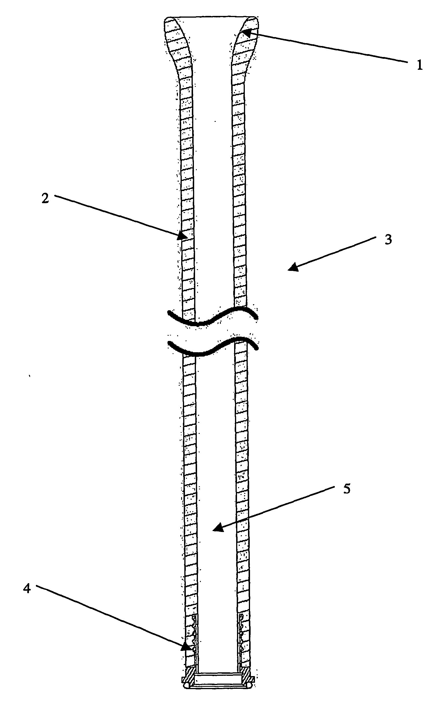
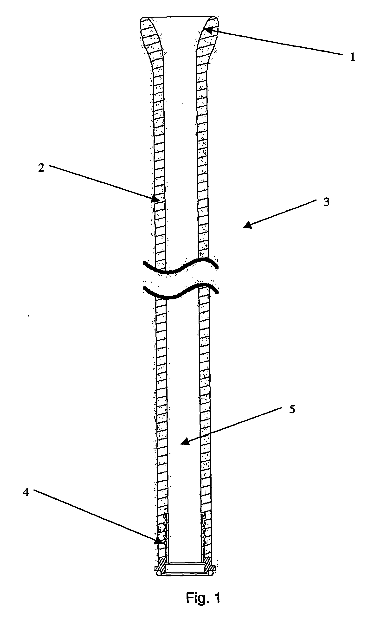
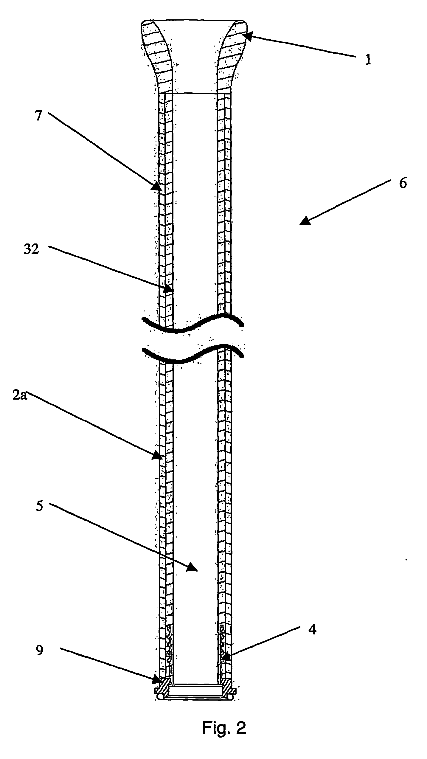
[0040] According to a further embodiment 33 shown in FIG. 4, locking nut 16 and sewing ring 14 may be slidably mounted on the cannula assembly. The cannula may be attached to the heart by first coring a suitable sized hole in the apex of the left ventricle or other suitable location and then inserting funnel-shaped end 1 into the heart a distance of approximately 20 mm, or as required by surgical technique into the heart. The sewing ring 14 may then be slid up the cannula until it touches the heart where it is snared around the shank of the cannula and then sewn to a ring of pledgets placed around the base of the ventricle. The adherence of the pledgets to the myocardium may be augmented by the use of fast curing bio-glue.
[0041] Please note that the sewing ring 14 is preferably constructed of velour or plastic. If the sewing ring 14 is constructed of a relatively hard or rigid material (such as relatively rigid plastic), the sewing ring 14 may include suture holes (not shown). Pleas...
embodiment 24
[0051]FIG. 7 shows a further embodiment 24 according to the present invention. Preferably in this embodiment, a positioning strip 23 is attached or integrally inserted within the lumen 2. This strip 23 allows for the orientation of the cannula to be determined when implantation is taking place. Alternatively, the positioning strip 23 could be replaced by a radiopaque region to allow the orientation and position of cannula to be determined by radiographic means.
[0052] Preferably, the cannula 24 illustrated in FIG. 7 includes sensors 25 within the lumen 2. These sensors 25 are capable of detecting and / or measuring blood flow rates and / or pressures within the shank of the cannula. These sensors 25 may preferably include a piezoelectric or ultrasonic detector to measure blood pressure and / or flow within the tubular shank of the embodiment. It should be understood that these sensors 25 are preferably encapsulated within the lumen 2 in such a manner that they do not contact the blood flow...
PUM
 Abstract
Description
Claims
Application Information
 - R&D
- Intellectual Property
- Life Sciences
- Materials
- Tech Scout
- Unparalleled Data Quality
- Higher Quality Content
- 60% Fewer Hallucinations
Browse by: Latest US Patents, China's latest patents, Technical Efficacy Thesaurus, Application Domain, Technology Topic, Popular Technical Reports.
© 2025 PatSnap. All rights reserved.Legal|Privacy policy|Modern Slavery Act Transparency Statement|Sitemap|About US| Contact US: help@patsnap.com


