Primary filter cleaning system for a dishwasher

a filter cleaning and dishwasher technology, applied in the field of dishwashers, can solve the problems of requiring a high-pressure wash system, wasting a great amount of water, energy and time to remove food, and fresh water quickly becoming soil-laden, and achieve the effect of convenient movemen

Inactive Publication Date: 2006-10-26
VIKING RANGE
View PDF6 Cites 73 Cited by
  • Summary
  • Abstract
  • Description
  • Claims
  • Application Information

AI Technical Summary

Benefits of technology

[0011] The present filter cleaning system incorporates a stationary manifold that is positioned about the upper periphery of the sump and that is in fluid communication with the pump. The generally circular manifold has multiple spaced-apart spray nozzles, with each of the nozzles aligned for spray contact with the filter. As described in detail below, the collection chamber is located off-center of the sump center, and hence, off-center of the bottom of the dishwasher. Each of the spray nozzles is

Problems solved by technology

However, the fresh water soon becomes soil-laden as the food soils are removed from the dishes.
This cycling approach, however, has several drawbacks, including expending a great amount of water, energy, and time to remove the food soil from the surfaces of the dishes, and requiring a high-flow pressure wash system.
Further, dishwashers that incorporate this cycling approach are relatively loud during drain and fill operations.
Where the primary dishwasher pump operates at a relatively high flow rate, however, keeping the filter clean and unblocked becomes increasingly difficult, especially when large amounts of food debris are suspended in the wash water.
This second type of filtration system is somewhat inefficient and ineffective since a portion of the suspended debris is re-pumped through the spray arms of the dishwasher and back onto the dishes, without first being filtered.
Further, the

Method used


Image

  • Primary filter cleaning system for a dishwasher
  • Primary filter cleaning system for a dishwasher
  • Primary filter cleaning system for a dishwasher

Examples


Embodiment Construction

[0022] Certain exemplary embodiments of the present invention are described below and illustrated in the attached Figs. The embodiments described are only for purposes of illustrating the present invention and should not be interpreted as limiting the scope of the invention, which, of course, is limited only by the claims below. Other embodiments of the invention, and certain modifications and improvements of the described embodiments, will occur to those skilled in the art, and all such alternate embodiments, modifications and improvements are within the scope of the present invention.

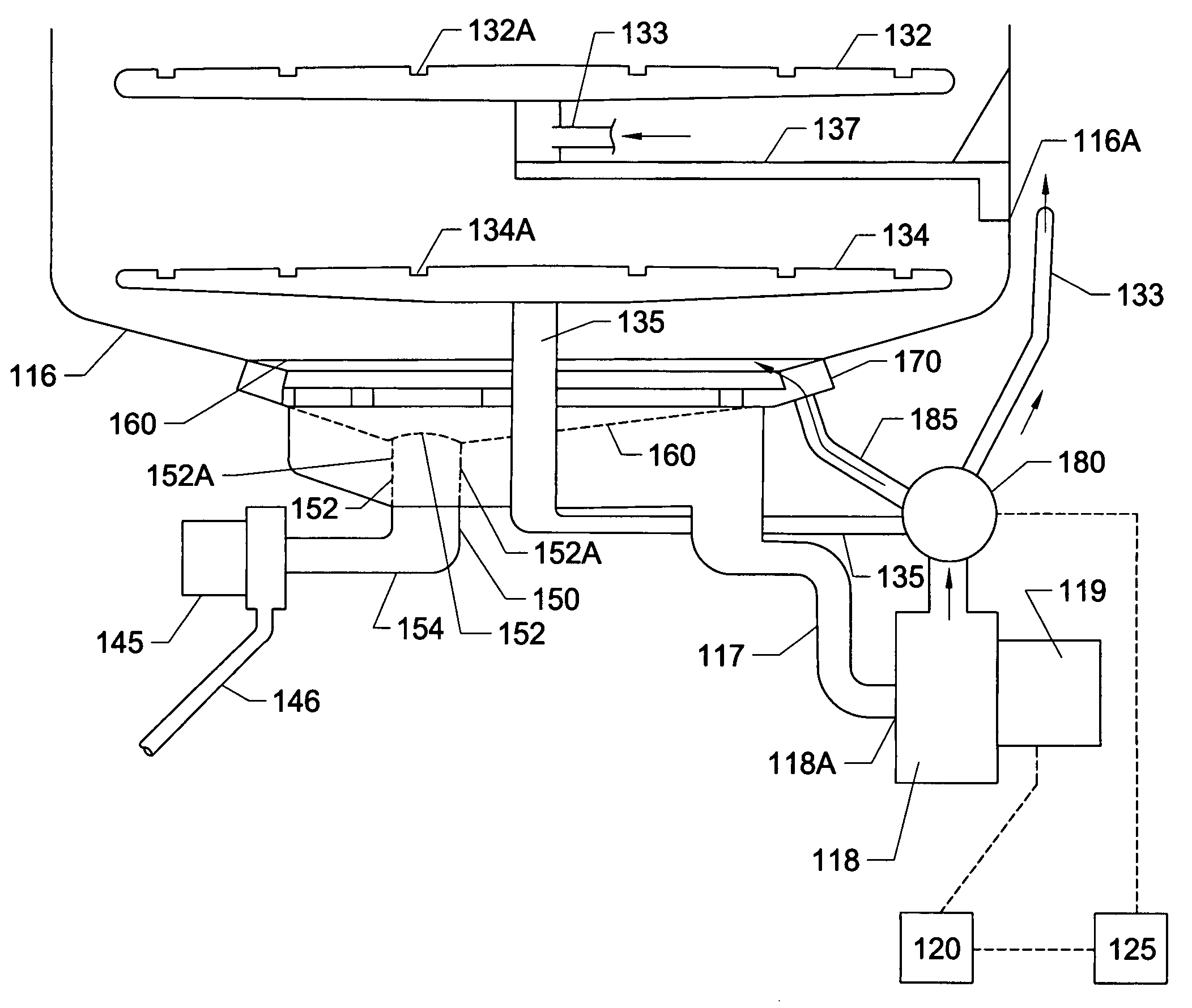
[0023] The present invention is directed to a dishwasher that addresses the problems in the prior art by incorporating a novel dishwasher that incorporates a primary filter cleaning system for removing food debris from the primary wash water filter of the dishwasher.

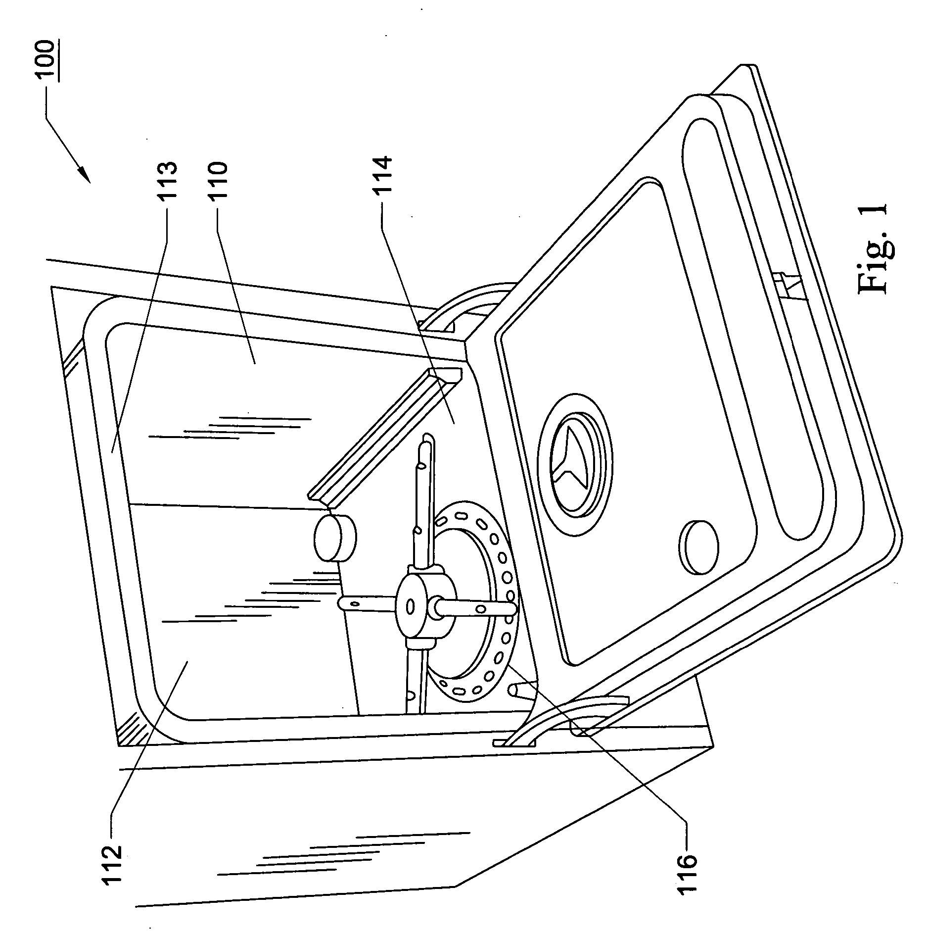
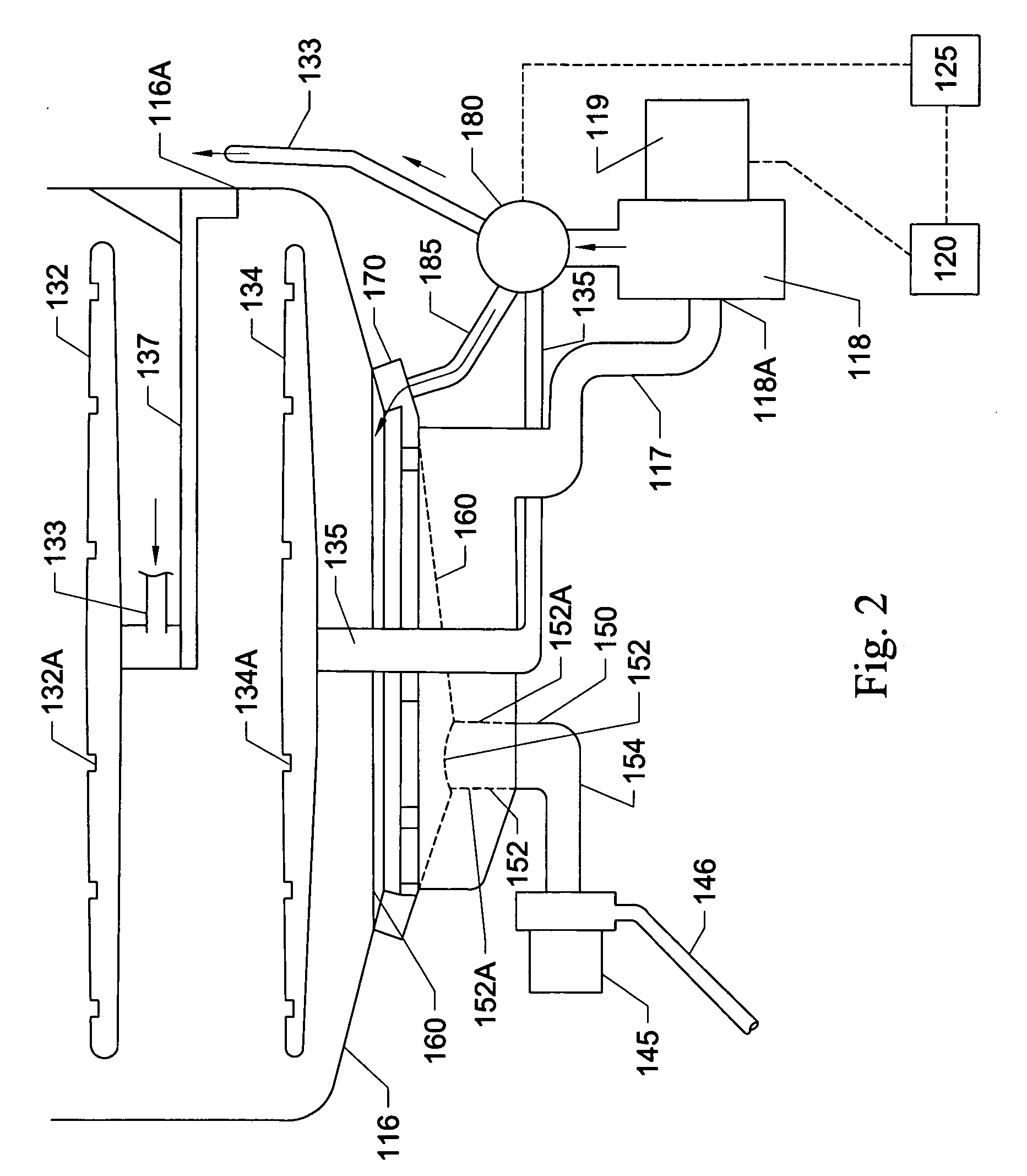
[0024] Referring to the Figs. in general, and FIGS. 1 and 2 in particular, a dishwasher 100 is shown. The dishwasher 100 includes oppos...


PUM

PropertyMeasurementUnit
Flow rateaaaaaaaaaa

Abstract

A dishwasher incorporates a primary filter cleaning system for removing food debris from circulated wash water. The dishwasher having a sump formed in the bottom and a wash pump having an inlet in communication with the sump. A collection chamber is formed through the bottom of the sump and a filter is situated over the top of the sump. The filter has an opening for depositing debris in the collection chamber. A stationary manifold is situated about the upper periphery of the sump and is aligned with the discharge of the pump. The manifold has multiple spaced spray nozzles, with each of the nozzles being aligned for spray contact with the filter. When water is pumped from the sump to the manifold, the water is sprayed across the filter to remove any food debris on the filter. The debris is then swept into the collection chamber.

Description

FIELD OF THE INVENTION [0001] The present invention relates generally to a dishwasher, and, more particularly, to a dishwasher that incorporates a filter cleaning system for a primary wash water filter. BACKGROUND OF THE INVENTION [0002] Conventional dishwashers utilize a drain and refill system that fills a dishwasher tub with fresh water at the beginning of the wash cycle to mix with and remove food soil from dishes. The cycle begins by drawing water through a pump that is controlled by a motor and that forces water onto dishes in the dishwasher through one or more spray arms. However, the fresh water soon becomes soil-laden as the food soils are removed from the dishes. The dishwashing cycle continues with the soil-laden water being drawn back into the pump through the pump inlet and sprayed back over the dishes. The dishwasher cycle then drains the soil-laden water from the dishwasher tub and repeats the cycle by refilling the tub with fresh water. This drain and refill sequence...

Claims


Application Information

Patent Timeline
IPC IPC(8): B08B7/04B08B3/04B08B3/00B08B3/12B08B9/20
CPCA47L15/4204A47L15/4221A47L15/4208A47L15/4206
Inventor WEAVER, DAVID CLINTONFERGUSON, JERRY WAYNEMORRISON, JOHN FREDERICKPICARDAT, JOHN PATRICK
Owner VIKING RANGE
Why Eureka
Try Eureka