
Computer-controlled system for dishwashers

a computer-controlled, dishwasher technology, applied in the direction of cleaning equipment, cleaning using liquids, sustainable buildings, etc., can solve the problems of not being able to detect and react to many variables/conditions inside the dishwasher, and the water temperature cannot reach the desired temperature for a very long time, so as to reduce or optimize the cycle time, water usage and wash performance

Inactive Publication Date: 2006-10-26
VIKING RANGE
View PDF13 Cites 56 Cited by
  • Summary
  • Abstract
  • Description
  • Claims
  • Application Information

AI Technical Summary

Benefits of technology

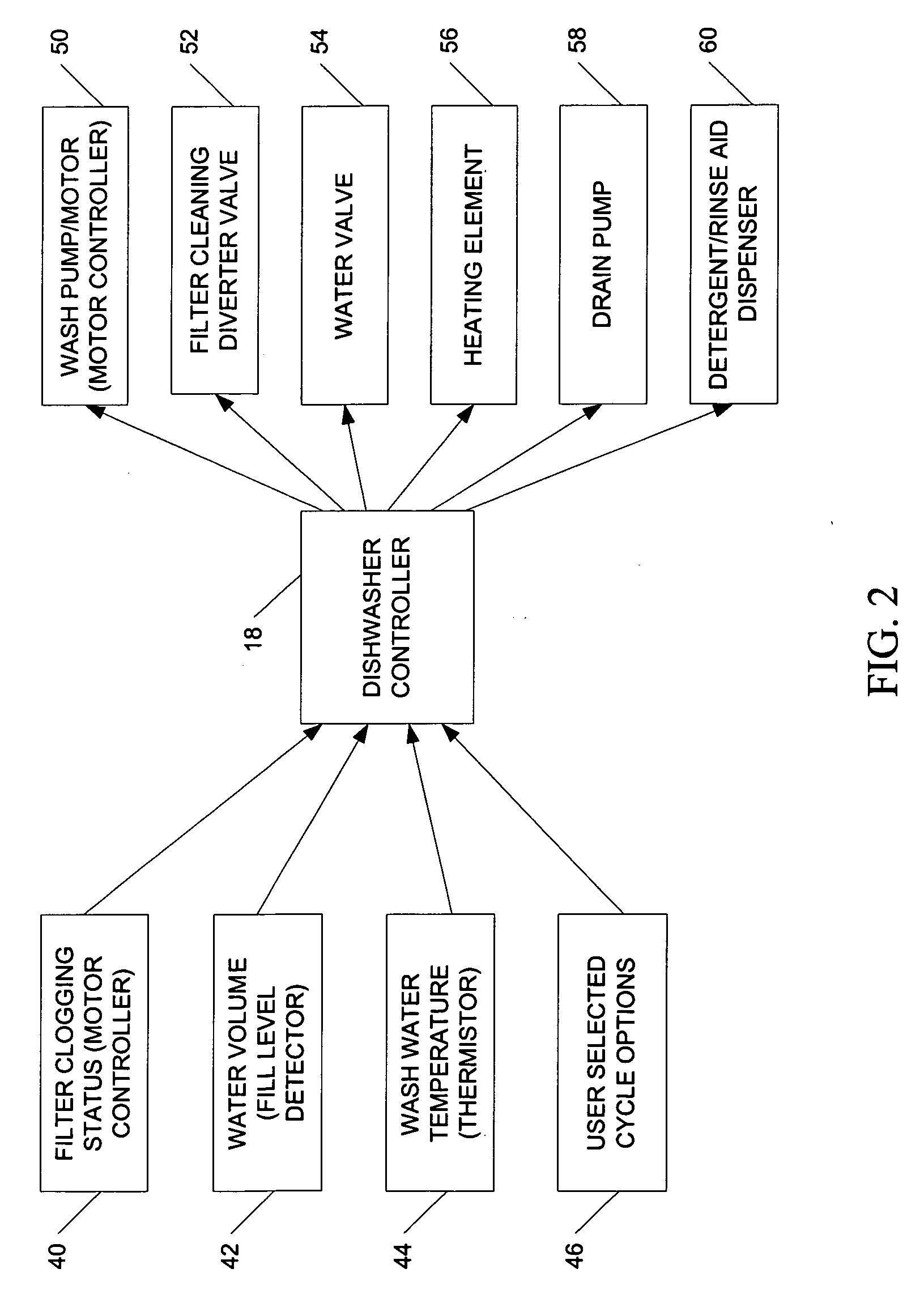
[0017] Once the information from these sensors and sources are collected the microprocessor can determine several key states within the machine and then react by changing the wash program in real-time. The real-time changes made to the wash system tend to minimize or (optimize) the cycle time, water usage and wash performance. Information collected also allows the microprocessor to determine if overflow or overheating conditions exist inside the machine and then react to correct those conditions.

Problems solved by technology

If the dishwasher was connected to cold water, it could take a very long time for the water to reach the desired temperature.
If there is not enough water in the machine there will be a characteristic pressure oscillation of the pump.
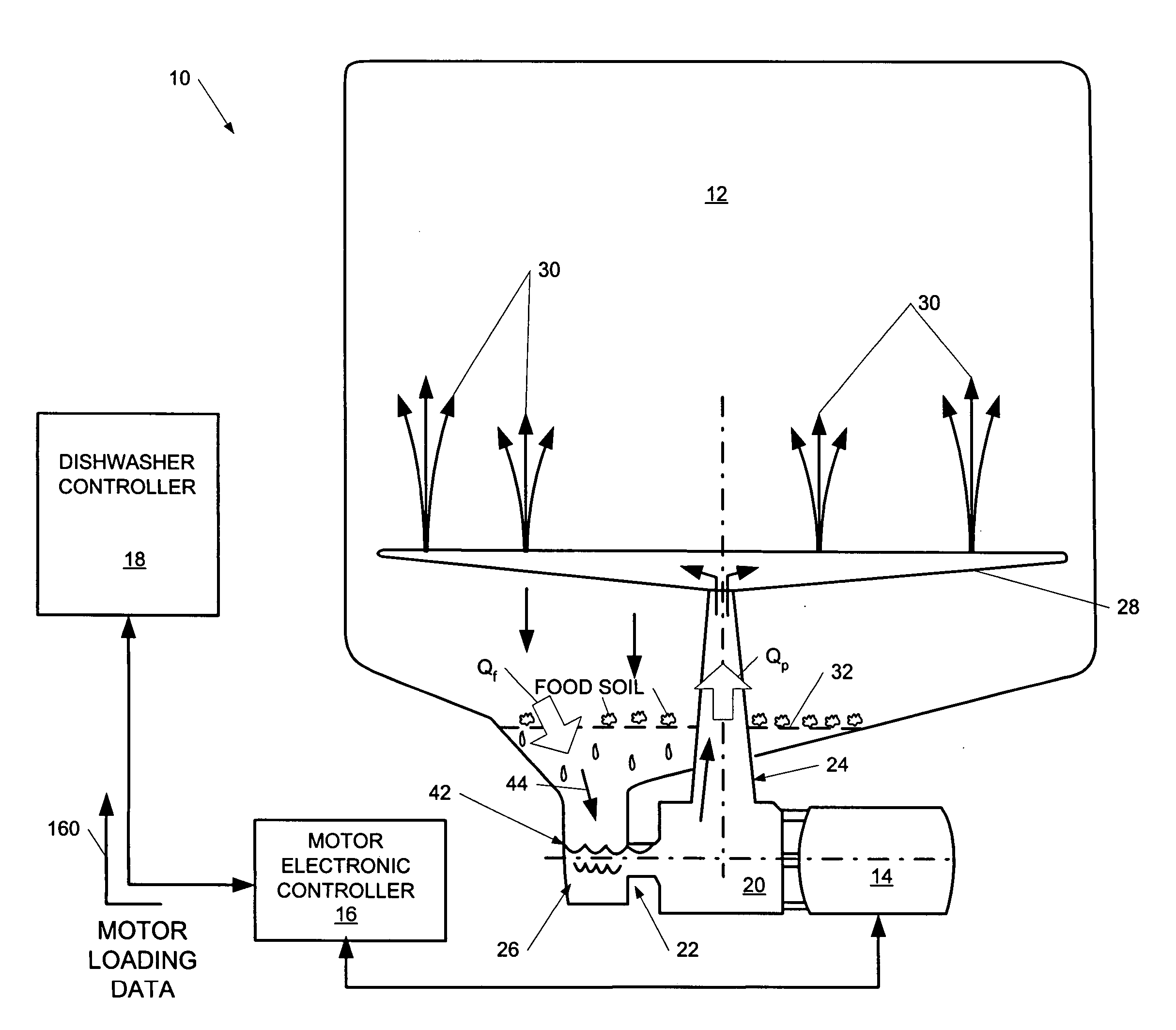
Most dishwasher controllers are unable to detect and react to many variables / conditions inside the dishwasher such as the surface area and thermal mass of dishes loaded into the dishwasher; the rate of change of the water temperature; the amount of food soil introduced into the dishwasher; the exact amount of water present in the dishwasher; and whether or not the “full flow” filtration system is allowing enough water to pass for the wash pump to operate at peak efficiency without losing prime.
The drawback of this “worst case, pre-programmed” approach is that it is wasteful of water, energy and time.
Currently none of the controls known in the art combines these many variables to optimize the cycle for high wash performance at the lowest possible water and energy usage.

Method used


Image

  • Computer-controlled system for dishwashers
  • Computer-controlled system for dishwashers
  • Computer-controlled system for dishwashers

Examples


Embodiment Construction

[0026] The following description of the invention is provided as an enabling teaching of the invention in its best, currently known embodiment. Those skilled in the relevant art will recognize that many changes can be made to the embodiments described, while still obtaining the beneficial results of the present invention. It will also be apparent that some of the desired benefits of the present invention can be obtained by selecting some of the features of the present invention without utilizing other features. Accordingly, those who work in the art will recognize that many modifications and adaptations to the present invention are possible and may even be desirable in certain circumstances and are a part of the present invention. Thus, the following description is provided as illustrative of the principles of the present invention and not in limitation thereof, since the scope of the present invention is defined by the claims.

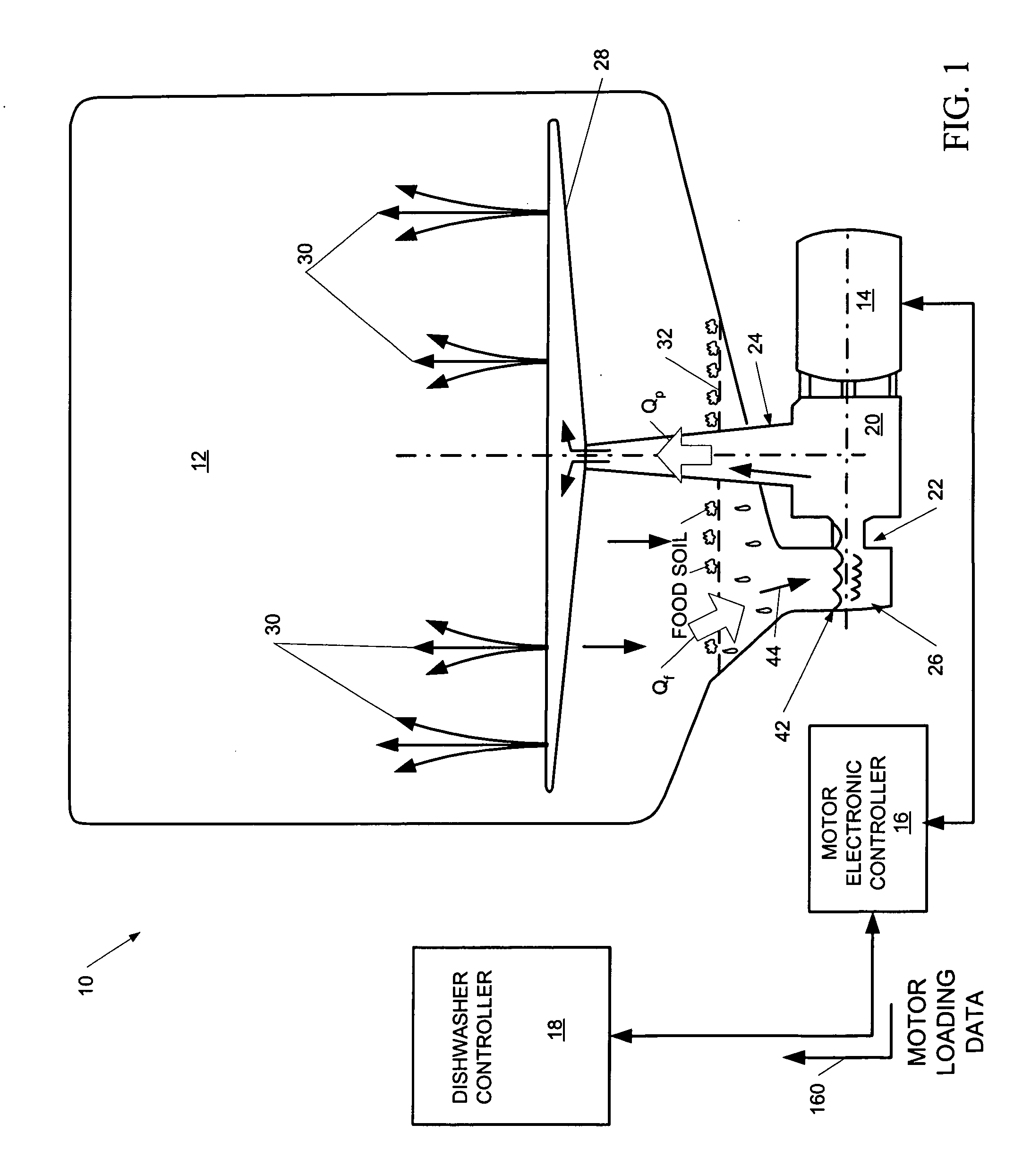
[0027]FIG. 1 illustrates an operational view of a dishw...


PUM

PropertyMeasurementUnit
Temperatureaaaaaaaaaa
Massaaaaaaaaaa
Speedaaaaaaaaaa

Abstract

A method and system for dynamically controlling operation of a dishwasher during a cleaning cycle. The method includes detecting a plurality of conditions in the dishwasher during operation, evaluating the plurality of detected conditions to determine a dynamic control response, and sending a signal representing the dynamic control response to at least one component of the dishwasher. The plurality of detected conditions can include some or all of a rate of change of a wash water temperature, an approximate surface area and thermal mass of a plurality of dishes loaded in the dishwasher, an amount of wash water added to the dishwasher and a status of a full flow filter. The control system includes means for detecting a plurality of conditions in the dishwasher during operation, means for evaluating the plurality of detected conditions to determine a dynamic control response, and means for sending a signal representing the dynamic control response to control at least one component of the dishwasher.

Description

CROSS-REFERENCE TO RELATED APPLICATION [0001] This application claims the benefit of U.S. Provisional Application 60 / 674,482, filed Apr. 25, 2005, incorporated by reference herein in its entirety.BACKGROUND OF INVENTION [0002] The present invention relates generally to dishwasher control systems and, more particularly to a dishwasher having a program-controlled controller providing dynamic control of dishwasher operation. [0003] Most dishwashers known in the art use some sort of electrical microprocessor or electromechanical device to control the functional components of the dishwasher. These components most commonly include the pump motor, drain motor, water heating element, water valve, detergent / rinse aid dispenser and often a few design-specific components such as electrically operated valves, etc. Historically, the most common inputs to these controls have been by the user setting inputs through the user interface control panel, temperature input from thermistors, or thermostat...

Claims


Application Information

Patent Timeline
IPC IPC(8): B08B7/04B08B3/00B08B9/20B08B3/04
CPCA47L15/0047Y02B40/42A47L15/4208A47L15/4221A47L15/4225A47L2301/04A47L2401/04A47L2401/08A47L2401/09A47L2401/10A47L2401/12A47L2501/01A47L2501/03A47L2501/05A47L2501/06A47L2501/07A47L2501/30A47L15/4204Y02B40/00
Inventor PICARDAT, JOHN PATRICKWEAVER, DAVID CLINTONFERGUSON, JERRY WAYNE
Owner VIKING RANGE
Learn More