Step motor valve assembly with fail-safe feature

a technology of stepper motor and valve assembly, which is applied in the direction of electrical control, instruments, horology, etc., can solve the problems that the type of mechanical return device does not lend itself to stepper motor valves

Inactive Publication Date: 2006-10-26
PARKER HANNIFIN CORP
View PDF11 Cites 34 Cited by
  • Summary
  • Abstract
  • Description
  • Claims
  • Application Information

AI Technical Summary

Benefits of technology

[0007] The present invention provides a mechanical fail-safe solution for step motor valves in which the opening and closing of the valve is effected by rotation of a rotor that not only rotates but also moves axially. The solution may be accomplished without the need for backup electrical power or separate fail-safe valves.
[0011] In a further embodiment, the return mechanism may include magnetically coupled first and second coupling members, the first coupling member being fixed for rotation with the rotor and the second coupling member being axially spaced from and magnetically coupled to the first coupling member such that the first and second coupling members commonly rotate; and a return device connected to the second coupling member for returning the second coupling member to a fail-safe position upon a loss of power to the step motor valve, whereupon the rotor and in turn the valve member will be moved to respective fail-safe positions. The return device may be located outside the shell with the second coupling member magnetically interacting with the first coupling member through a magnetically transparent wall portion of the shell. The second coupling member and return device may be mounted in a case that can be selectively attached to the shell, whereby the step motor valve assembly can operate without a fail-safe feature when the case is not attached to the shell and with a fail-safe feature when the case is attached to the shell.

Problems solved by technology

A major limitation of many step motor valves is that upon a loss of power they remain at their last commanded position.
In some applications this can be detrimental, i.e. the valve could be full open, full closed or any position in between.
If there is a power failure, the fail-safe valve will under the mechanical action of the spring move to its fail-safe position and override the step motor valve.
Such type of mechanical return device does not lend itself to stepper motor valves wherein the rotor assembly moves not only rotationally but also axially.

Method used


Image

  • Step motor valve assembly with fail-safe feature
  • Step motor valve assembly with fail-safe feature
  • Step motor valve assembly with fail-safe feature

Examples


Embodiment Construction

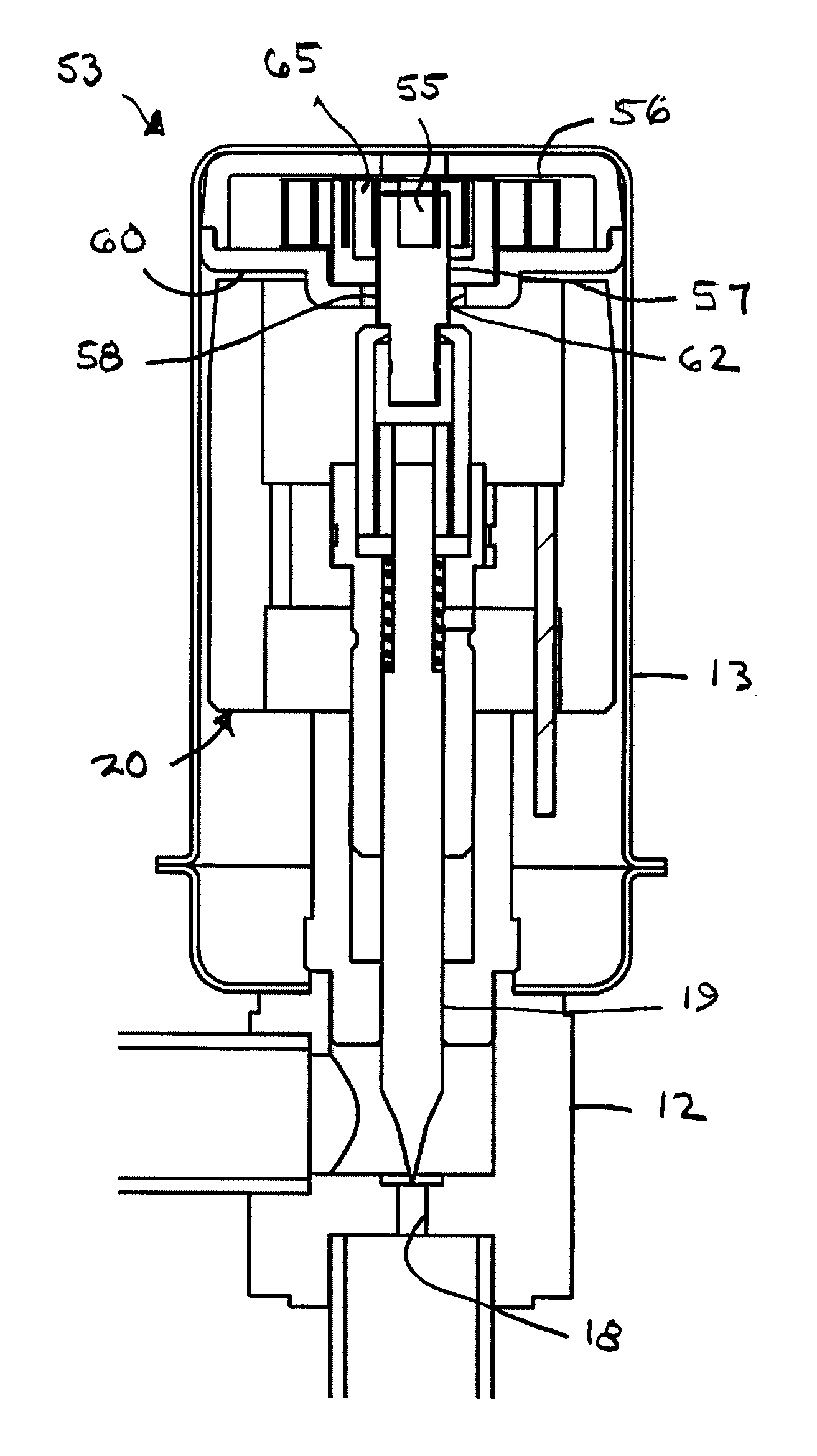
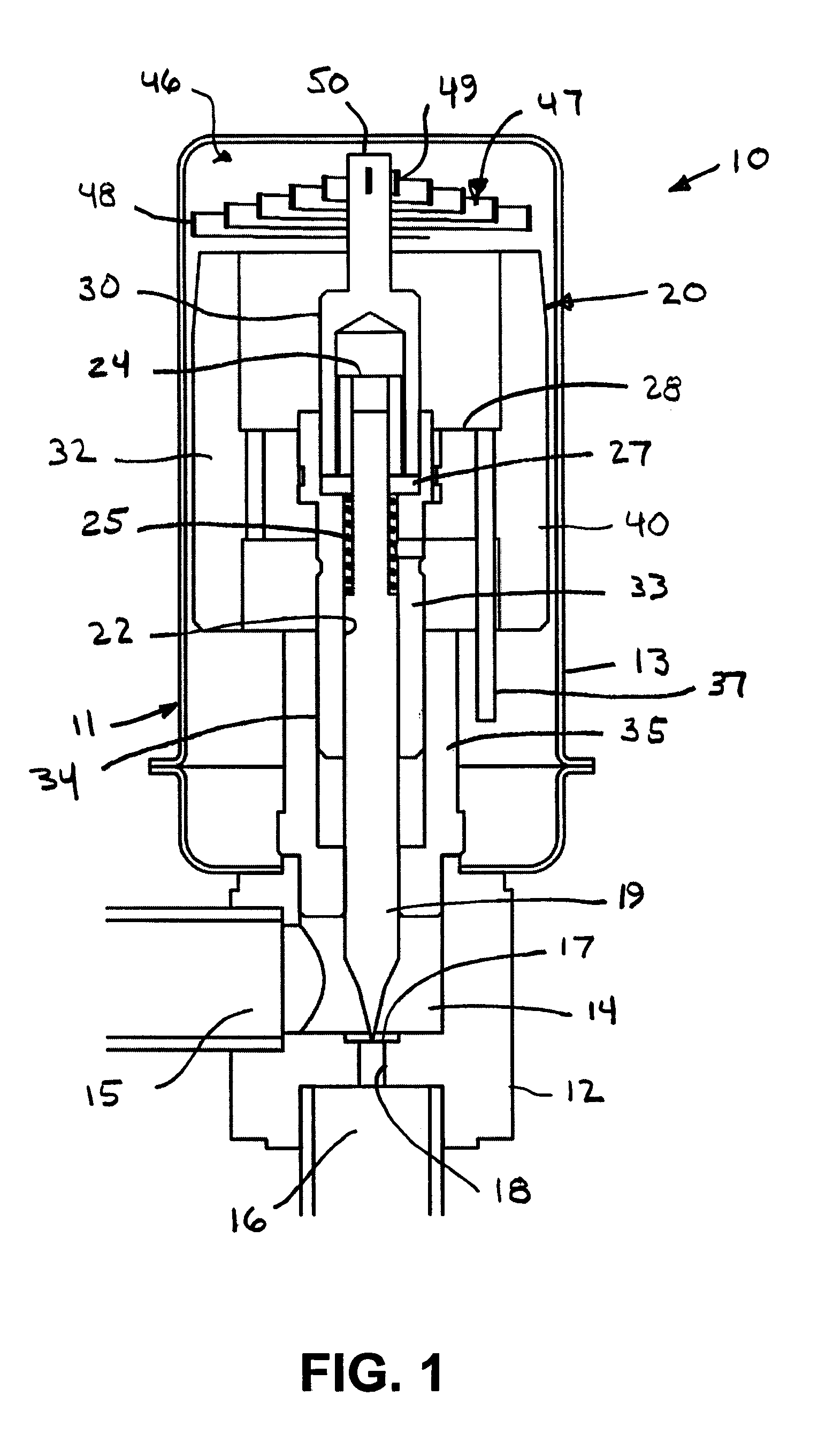
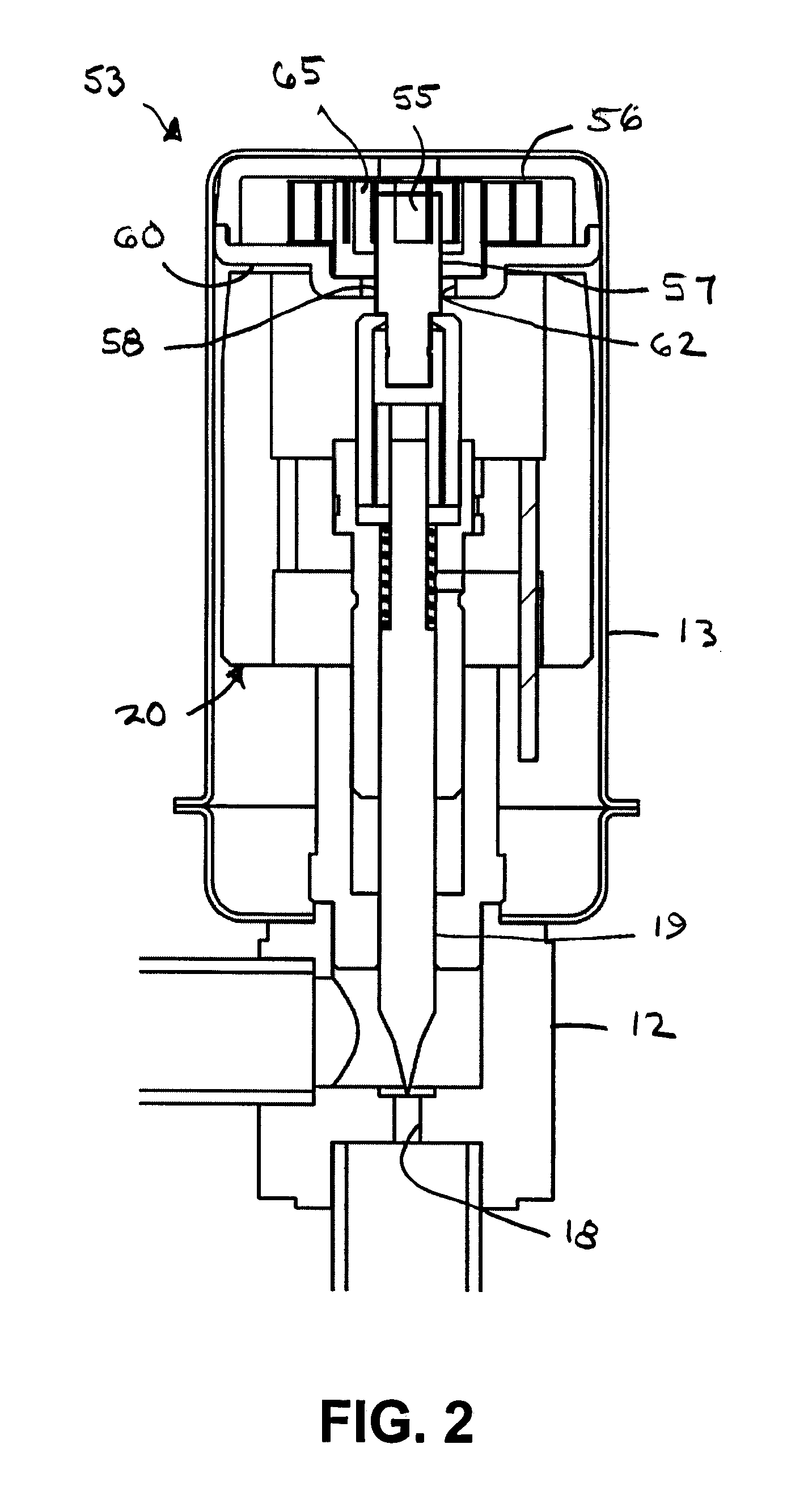
[0026] Referring now in detail the drawings and initially to FIG. 1, an exemplary step motor valve assembly according to the invention is designated generally by reference numeral 10. The illustrated step motor valve assembly 10 has particular application in a refrigeration cycle system and particularly as an expansion valve for controlling fluid flow to an expansion orifice. Although the invention is illustrated by reference to such type of valve, those skilled in the art will appreciate that the principles of the invention will have applicability to other types of step motor valves. In this specification reference may be had to upper, lower, above, below, etc. in relation to the orientation of the step motor valve assembly illustrated in the drawings. This is done as a matter of convenience inasmuch as the step motor can be otherwise oriented. Accordingly, such positional relationships are not intended to limit the step motor valve assembly to a particular orientation unless other...


PUM


Abstract

A step motor valve assembly comprises a housing including a threaded portion, a rotor having rotational axis and a threaded portion in threaded engagement with the threaded portion of the housing such that rotation of the rotor will effect axial movement of the rotor relative to the housing, a valve member carried by the rotor for axial movement toward and away from a valve seat upon rotation of the rotor in respective opposite directions, and a return mechanism for moving the valve member to a fail-safe position upon a loss of power to the step motor valve assembly.

Description

RELATED APPLICATION [0001] This application claims the benefit of U.S. Provisional Application No. 60 / 668,903 filed Apr. 6, 2005, which is hereby incorporated herein by reference in its entirety.FIELD OF THE INVENTION [0002] The invention herein described relates generally to step motor valve assemblies and more particularly to a step motor valve assembly with a failsafe feature. BACKGROUND [0003] Step motor valves, also referred to as stepper motor valves, are used to control a variety of fluids in industrial systems. A major limitation of many step motor valves is that upon a loss of power they remain at their last commanded position. In some applications this can be detrimental, i.e. the valve could be full open, full closed or any position in between. Electrical battery or capacitor back-up system solutions heretofore have been proposed to supply emergency power to the stepper drive to force it to a known, desired fail-safe position. [0004] Another solution has been to include i...

Claims


Application Information

Patent Timeline
Patent Type & Authority Applications(United States)
IPC IPC(8): H02K37/14H02K7/06F16K31/02
CPCF16K31/047H02K37/24H02K7/06
Inventor NIEDERMEYER, JOHN F.WYCOFF, LYMAN W.
Owner PARKER HANNIFIN CORP
Why Eureka
Try Eureka