
Personal status physiologic monitor system and architecture and related monitoring methods

a monitoring system and physiologic technology, applied in the field of patient monitoring systems, can solve the problems of high cost of current technology and too costly traditional methods for early detection to be broadly deployed, and achieve the effect of preserving battery life and reducing cos

Active Publication Date: 2006-10-26
WELCH ALLYN INC
View PDF8 Cites 329 Cited by
  • Summary
  • Abstract
  • Description
  • Claims
  • Application Information

AI Technical Summary

Benefits of technology

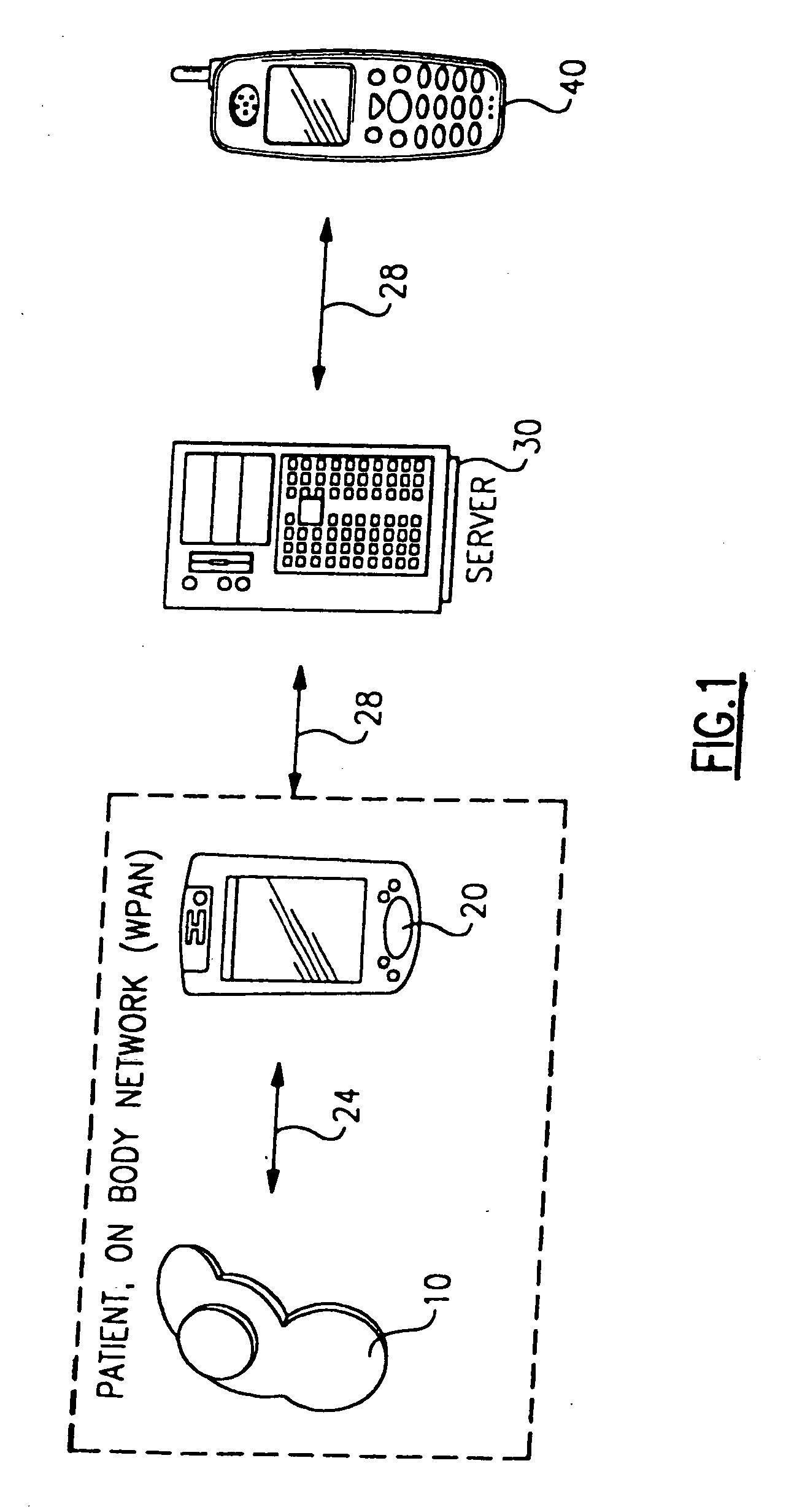
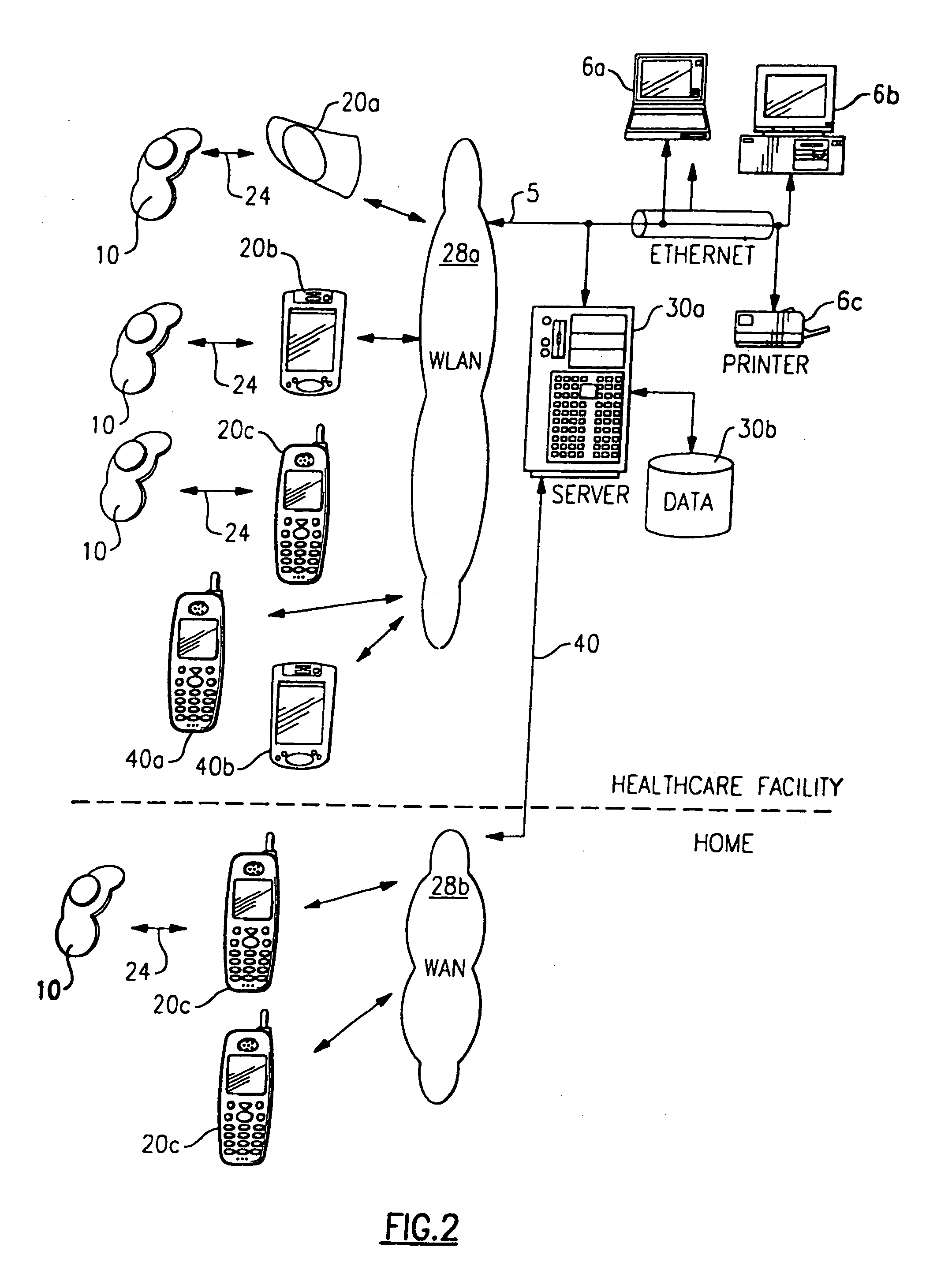
The present invention is a system for actively monitoring a patient's physiologic parameters and detecting specific events. The system includes a body-worn monitoring device with sensors that measure various physiologic parameters and detect specific events. An intermediary device is connected to the monitoring device through a network, and a computer is connected to the intermediary device through a network. The system also includes a respondent device that can automatically perform specific functions when a predetermined event is detected. The system can also include a wireless network for transmitting data between the monitoring device and the intermediary device. Additionally, the invention includes a method for appending a unique patient identifier to a continuous physiologic signal and disassociating it from the signal when a change occurs. The technical effects of the invention include improved patient monitoring and management, as well as improved data transmission and analysis.

Problems solved by technology

Traditional methods for early detection are too costly to be broadly deployed.
The capital cost of current technology is approximately $.12,000 to $30,000 per device and requires high technical skill levels to use the devices and related systems effectively.
Hardwired systems expanded in the hospital as medical care subspecialties grew, but were generally restricted to intensive care settings.

Method used


Image

  • Personal status physiologic monitor system and architecture and related monitoring methods
  • Personal status physiologic monitor system and architecture and related monitoring methods
  • Personal status physiologic monitor system and architecture and related monitoring methods

Examples


Embodiment Construction

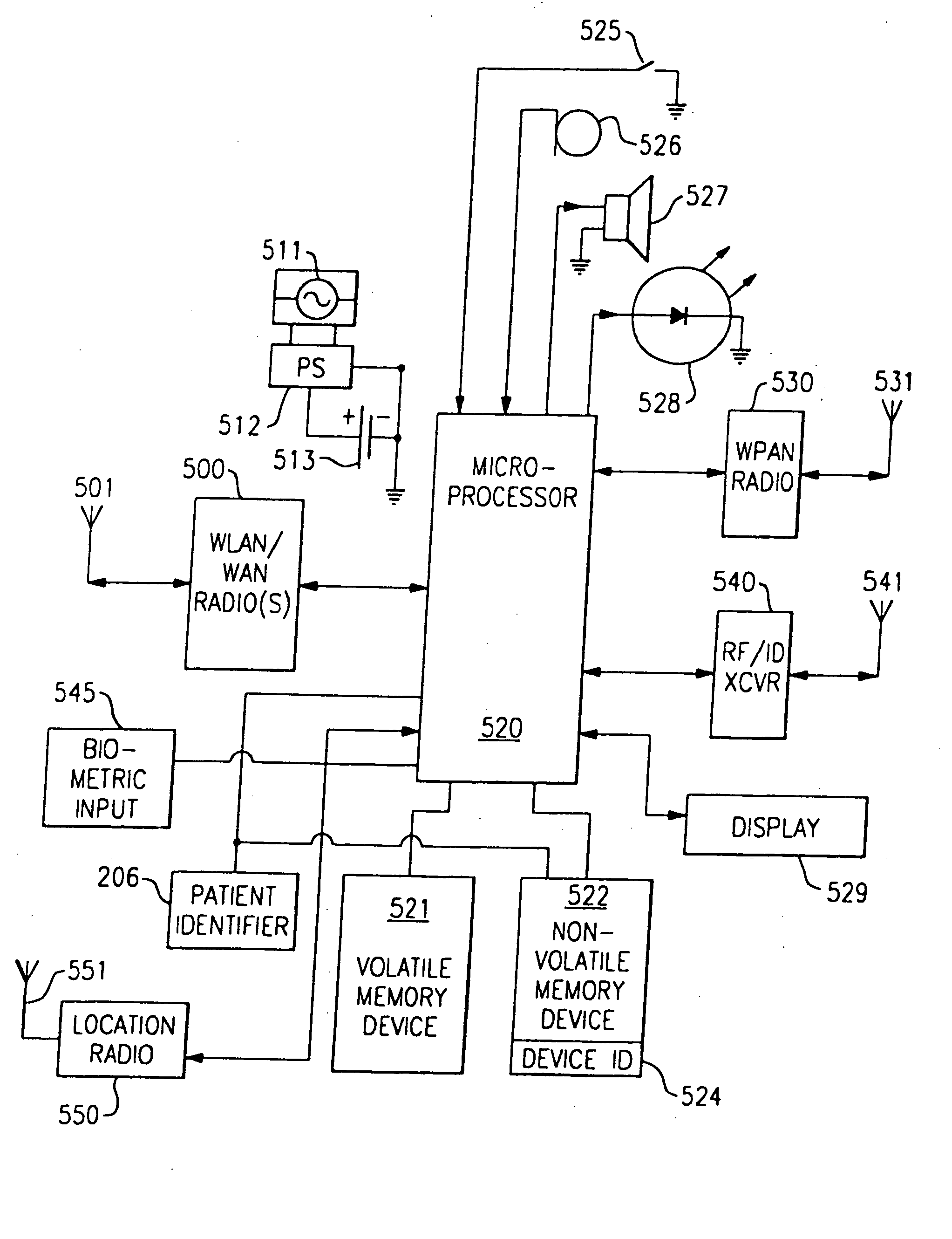
[0073] The following description relates to an event monitoring systems architecture according to a preferred embodiment of the present invention. Certain terms are used throughout the discussion, such as, for example, “top”, “bottom”, “upper”, “lower” and the like in order to provide a convenient frame of reference with regard to the accompanying drawings. These terms, however, unless specifically indicated otherwise, are not intended to be over limiting of the present invention.

[0074] Throughout the course of the discussion, various terms are used that require additional definitions for clarity.

[0075] By “body-worn device,” it is meant that the device is entirely worn on the body of the patient wherein the device is affixed or otherwise attached directly to the skin of the patient.

[0076]“Network” refers to a communications linkage between at least two devices. Unless stated otherwise, this linkage can be wireless or hardwired in nature or both.

[0077] A “patient-worn” device re...


PUM


Abstract

A method for performing context management, said method comprising the steps of: producing a continuous physiologic signal, as detected by a monitoring device; associating at least one unique hardware identifier to said continuous physiologic signal and binding a unique patient identifier to said continuous signal wherein a change in said physiologic signal in which said signal is no longer continuous will cause the unique patient identifier to unbind from said signal.

Description

CROSS REFERENCE TO RELATED APPLICATIONS [0001] This application is a divisional application of U.S. patent application Ser. No. 11 / 03 1,736, filed Jan. 7, 2005, which is a continuation application under 35 USC §120 claiming benefit of U.S. Ser. No. 10 / 806,770, filed Mar. 22, 2004, which is a non-provisional patent application claiming priority under 35 USC §119 (e)(1) to U.S. Ser. No. 60 / 456,609, filed, Mar. 21, 2003, entitled “Personal Status Physiologic Monitor System and Architecture” and U.S. Ser. No. 60 / 554,706, filed Mar. 20, 2004, entitled “Personal Status Physiologic Monitor System and Architecture and Related Monitoring Methods”, the contents of each of which are herein incorporated in their entirety.FIELD OF THE INVENTION [0002] This invention relates generally to patient monitoring systems, and more specifically to an improved patient monitoring system architecture. BACKGROUND OF THE INVENTION [0003] Over 1.1 million Americans experience a cardiac arrest each year. Of tha...

Claims


Application Information

Patent Timeline
Patent Type & Authority Applications(United States)
IPC IPC(8): G08B1/08A61B5/00A61B5/332G08B21/04G16H40/67G16Z99/00
CPCA61B5/0024A61B2505/01A61B5/0402A61B5/0404A61B5/1113A61B5/113A61B5/145A61B5/1455A61B2560/0209A61B2562/0219G06F19/323G06F19/3406G06F19/3418G08B21/04G08B21/0446G08B21/0453A61B5/7232A61B5/002A61B5/01G16H40/63G16H10/65G16H40/67A61B5/332A61B5/318G16Z99/00
Inventor WELCH, JAMES P.BAKER, STEVEN D.GUILAK, FARZIN G.SAMPATH, ANANDWILLIAMS, DANIEL L.
Owner WELCH ALLYN INC
Learn More