
Operation microscope apparatus

Active Publication Date: 2006-10-26
KK TOPCON
View PDF2 Cites 14 Cited by
  • Summary
  • Abstract
  • Description
  • Claims
  • Application Information

AI Technical Summary

Benefits of technology

[0027] The present invention has been made in view of the above-mentioned circumstances. An object of the present invention is to provide an operation microscope apparatus capable of easily and speedily obtaining a suitable separation state between illumination light and observation light in a case where a front lens is replaced by another one.
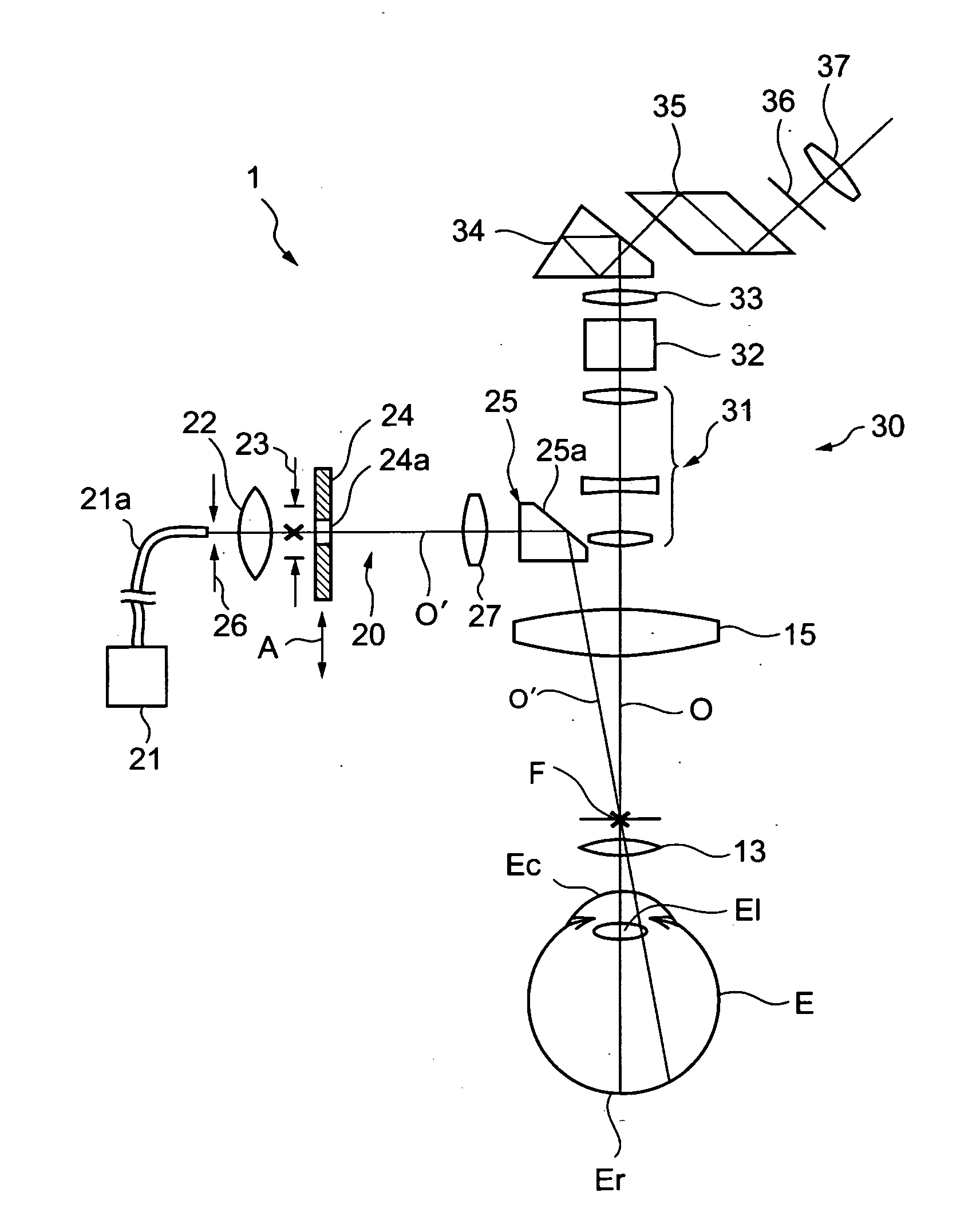
[0028] In order to achieve the above-mentioned object, according to a first aspect of the present invention, an operation microscope apparatus is characterized by including: an illumination optical system for emitting illumination light to an eye to be operated at a predetermined illumination angle; an objective lens; a front lens for condensing the illumination light from the illumination optical system to illuminate an interior of the eye to be operated, the front lens being provided in a use position between the eye to be operated and a front focus point of the objective lens in which a plurality of front lenses having different refractive powers are selectively located; an observation optical system including an eyepiece, for guiding, to the eyepiece, reflection light of the illumination light from the eye to be operated through the front lens and the objective lens; input means for inputting identification information for identifying the front lens located in the use position, of the plurality of front lenses; and control means for controlling the illumination optical system to set an illumination angle of the illumination light to an illumination angle corresponding to the inputted identification information. When the identification information for identifying the front lens located in the use position, of the plurality of front lenses is inputted, the illumination angle of the illumination light is automatically set to the illumination angle corresponding to the identification information. Therefore, there is an effect in that a suitable separation state between illumination light and observation light can be easily and speedily obtained corresponding to the used front lens.
[0029] According to a second aspect of the present invention, an operation microscope apparatus is characterized by including: an illumination optical system for emitting illumination light to an eye to be operated at a predetermined illumination angle, the illumination optical system including slit means for adjusting a slit width of a slit for transmitting a part of the illumination light, the slit being formed in the slit means; an objective lens; a front lens for condensing the illumination light from the illumination optical system to illuminate an interior of the eye to be operated, the front lens being provided in a use position between the eye to be operated and a front focus point of the objective lens in which a plurality of front lenses having different refractive powers are selectively located; an observation optical system including an eyepiece, for guiding, to the eyepiece, reflection light of the illumination light from the eye to be operated through the front lens and the objective lens; input means for inputting identification information for identifying the front lens located in the use position, of the plurality of front lenses; and control means for controlling the slit means to set the slit width of the slit to a slit width corresponding to the inputted identification information. When the identification information for identifying the front lens located in the use position, of the plurality of front lenses is inputted, the slit width of the slit is automatically set to a slit width corresponding to the identification information. Therefore, there is an effect in that a suitable separation state between illumination light and observation light can be easily and speedily obtained corresponding to the used front lens.
[0030] According to a third aspect of the present invention, an operation microscope apparatus is characterized by including: an illumination optical system for emitting illumination light to an eye to be operated at a predetermined illumination angle, the illumination optical system including slit means for adjusting a slit width of a slit for transmitting a part of the illumination light, the slit being formed in the slit means; an objective lens; a front lens for condensing the illumination light from the illumination optical system to illuminate an interior of the eye to be operated, the front lens being provided in a use position between the eye to be operated and a front focus point of the objective lens in which a plurality of front lenses having different refractive powers are selectively located; an observation optical system including an eyepiece, for guiding, to the eyepiece, reflection light of the illumination light from the eye to be operated through the front lens and the objective lens; input means for inputting identification information for identifying the front lens located in the use position, of the plurality of front lenses; and control means for controlling the illumination optical system to set an illumination angle of the illumination light to an illumination angle corresponding to the inputted identification information and controlling the slit means to set the slit width of the slit to a slit width corresponding to the inputted identification information. When the identification information for identifying the front lens located in the use position, of the plurality of front lenses is inputted, the illumination angle of the illumination light is automatically set to the illumination angle corresponding to the identification information and the slit width of the slit is automatically set to a slit width corresponding to the identification information. Therefore, there is an effect in that a suitable separation state between illumination light and observation light can be easily and speedily obtained corresponding to the used front lens.

Problems solved by technology

This raises a problem in that, for example, it is difficult to perform a fine operation.
However, for example, when the operator is not a skilled operator, it is difficult to realize the suitable separation states.
Therefore, every time the front lens 13 is replaced by another one, it is necessary to adjust an illumination angle of the illumination light and a slit width to ensure the suitable separation state, so that the manipulation is troublesome.
When the front lens 13 is replaced by another one for the operation, it takes a time to ensure the separation state, with the result that it is likely to unnecessarily prolong the operation.

Method used


Image

  • Operation microscope apparatus
  • Operation microscope apparatus
  • Operation microscope apparatus

Examples


first embodiment

[External Structure]

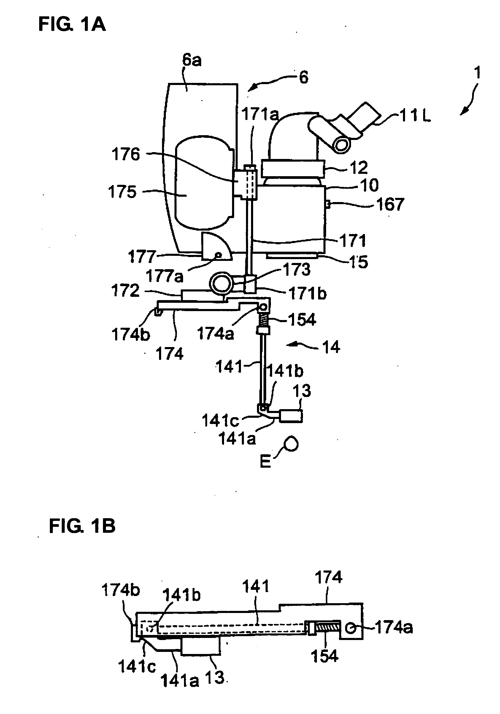
[0051] An operation microscope apparatus according to a first embodiment of the present invention has the same external structure as that of a conventional operation microscope apparatus (see FIG. 14). An operation microscope apparatus 1 according to the first embodiment of the present invention includes a pillar 2 for supporting the operation microscope apparatus 1, a first arm 3 whose one end is connected with an upper end of the pillar 2, a second arm 4 whose one end is connected with the other end of the first arm 3, a drive device 5 connected with the other end of the second arm 4, an operator's microscope 6 suspended from the drive device 5, an assistant's microscope 7 provided adjacent to the operator's microscope 6, and a foot switch 8 for performing various manipulations by a foot.

[0052] The operator's microscope 6 includes a main body section 6a, a lens barrel section 10 housing, for example, various optical systems and various drive systems. An inver...


PUM


Abstract

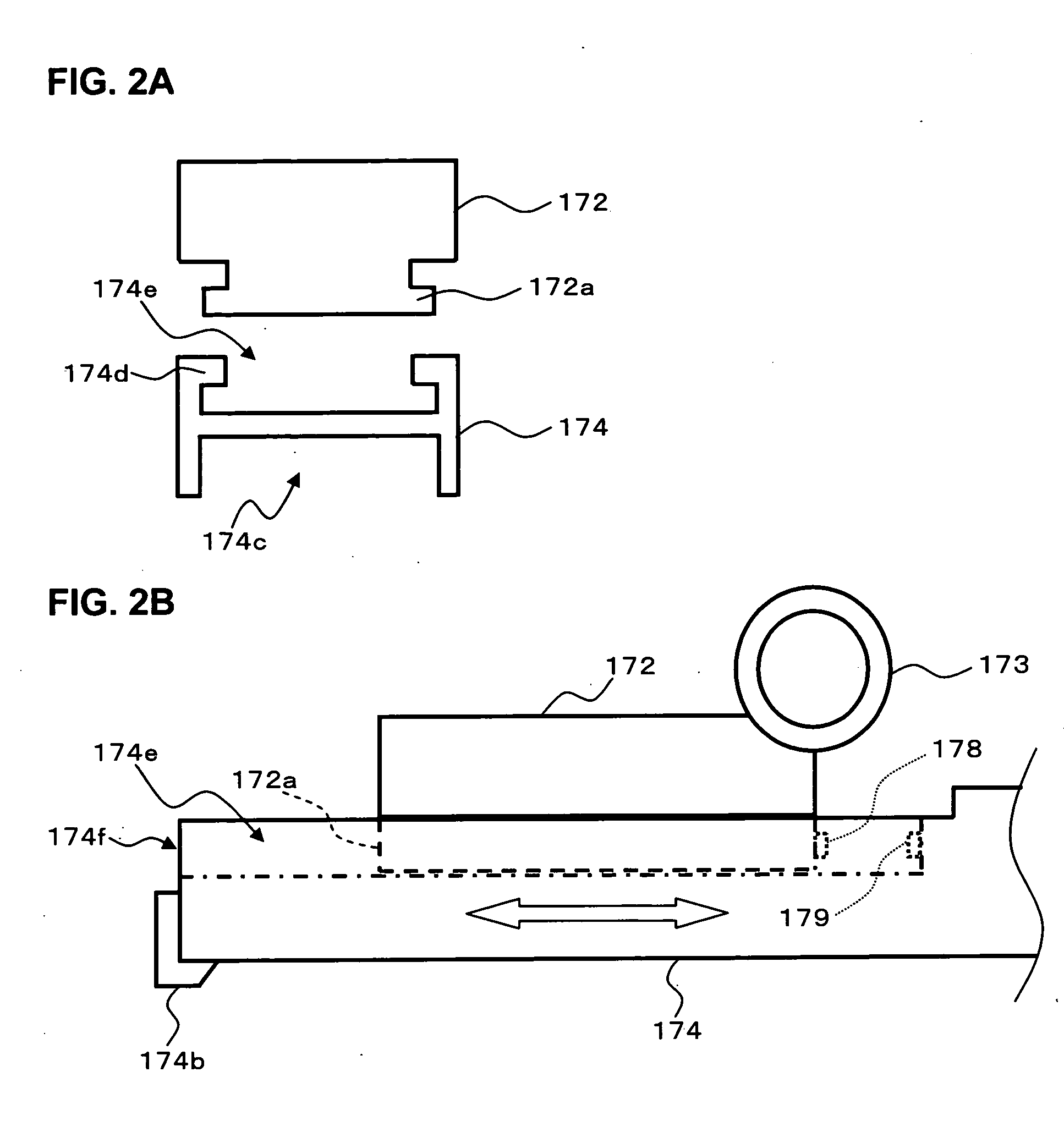
Provided is an operation microscope apparatus for easily and speedily obtaining a suitable separation state between illumination light and observation light in a case where a front lens is replaced by another one. An illumination optical system includes a slit plate in which slit holes having different slit widths are formed. Each of a plurality of front lens having different refractive powers is integrally formed with corresponding one of storing sections. One of the storing sections is attached to an elevation regulating member. The elevation regulating member includes micro-switches. Each of the storing sections includes a protruding portion for turning on corresponding one of the micro-switches at the time of attachment. A control unit sets an illumination angle of the illumination light and a slit width of a slit based on a detection signal from a micro-switch which becomes an on state.

Description

BACKGROUND OF THE INVENTION [0001] 1. Field of the Invention [0002] The present invention relates to an operation microscope apparatus used for an ophthalmologic operation, and more particularly, to an operation microscope apparatus including a front lens for condensing illumination light to illuminate an interior of an eye. [0003] 2. Description of the Related Art [0004] Up to now, when a retina and vitreous body operation in an ophthalmologic field is performed, as shown in FIG. 13, an operation contact lens 200 is placed on a cornea Ec of an eye to be operated E. Then, while a light guide (optical fiber) 201 is inserted into an interior of the eye to illuminate an operation region, an operation instrument 202 such as a cutter or a forceps is inserted into the interior of the eye to perform the operation. In FIG. 13, reference symbol Ec denotes the cornea and Ev denotes a vitreous chamber. When the operation is to be performed using the operation method as shown in FIG. 13, it is ...

Claims


Application Information

Patent Timeline
IPC IPC(8): A61B3/10
CPCA61F9/007A61B3/135
Inventor KITAJIMA, NOBUAKI
Owner KK TOPCON
Learn More