All-optical signal processing method and device

a technology of optical signal processing and optical device, applied in the field of all-optical filter, can solve the problems of degrading optical signal quality, affecting the quality of optical signal, and generating additional cost in the back and forth, and achieve the effect of adequate signal level and operation, cost saving and adequate signal level

Inactive Publication Date: 2006-10-26
LUXDYNE
View PDF4 Cites 35 Cited by
  • Summary
  • Abstract
  • Description
  • Claims
  • Application Information

AI Technical Summary

Benefits of technology

[0011] The significant benefits of the invention include, for example, the fact that the present invention can be used to realize optical devices that process multiple wavelength channels simultaneously, that is to say in parallel. The invention requires that the optical length of one polarization mode of the resonator arrangement is matched with the wavelength of the incoming light, but it has no temporal signal length requirements, i.e. requirements for the duration regarding the rate of the incoming optical data. The data rate is matched by selecting, for example, suitable amount of birefringence into the resonator. The method of the invention thus enables parallel processing of multiple wavelengths simultaneously, provided that the resonator length is matched to all used wavelengths and the birefringence is suitable for the data rate.

Problems solved by technology

The conversions forth and back generate also additional cost and possibly degrade optical signal quality.
The device is, however, very limited in its capabilities to process more than one wavelength (or WDM channel) at time.

Method used


Image

  • All-optical signal processing method and device
  • All-optical signal processing method and device
  • All-optical signal processing method and device

Examples


Embodiment Construction

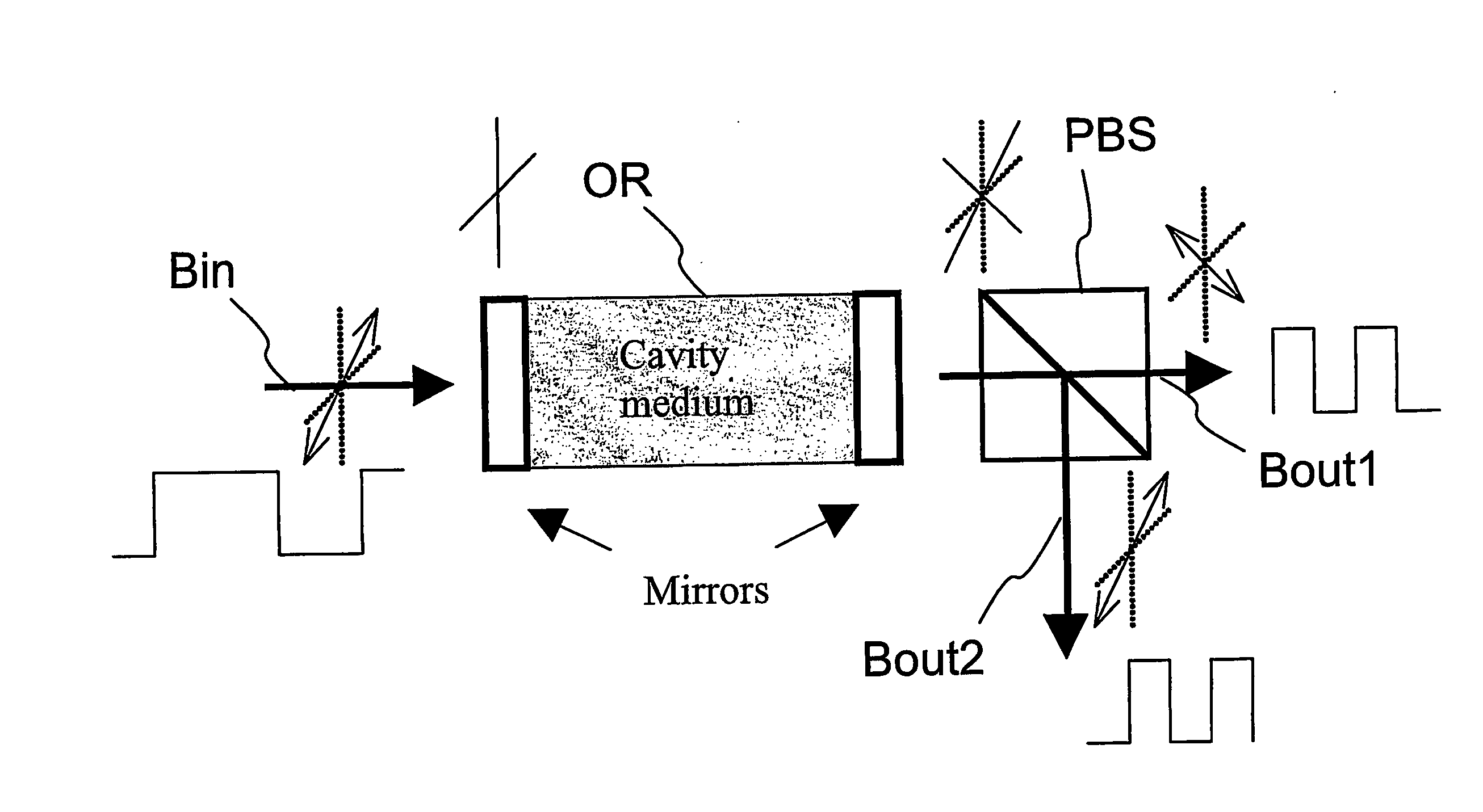
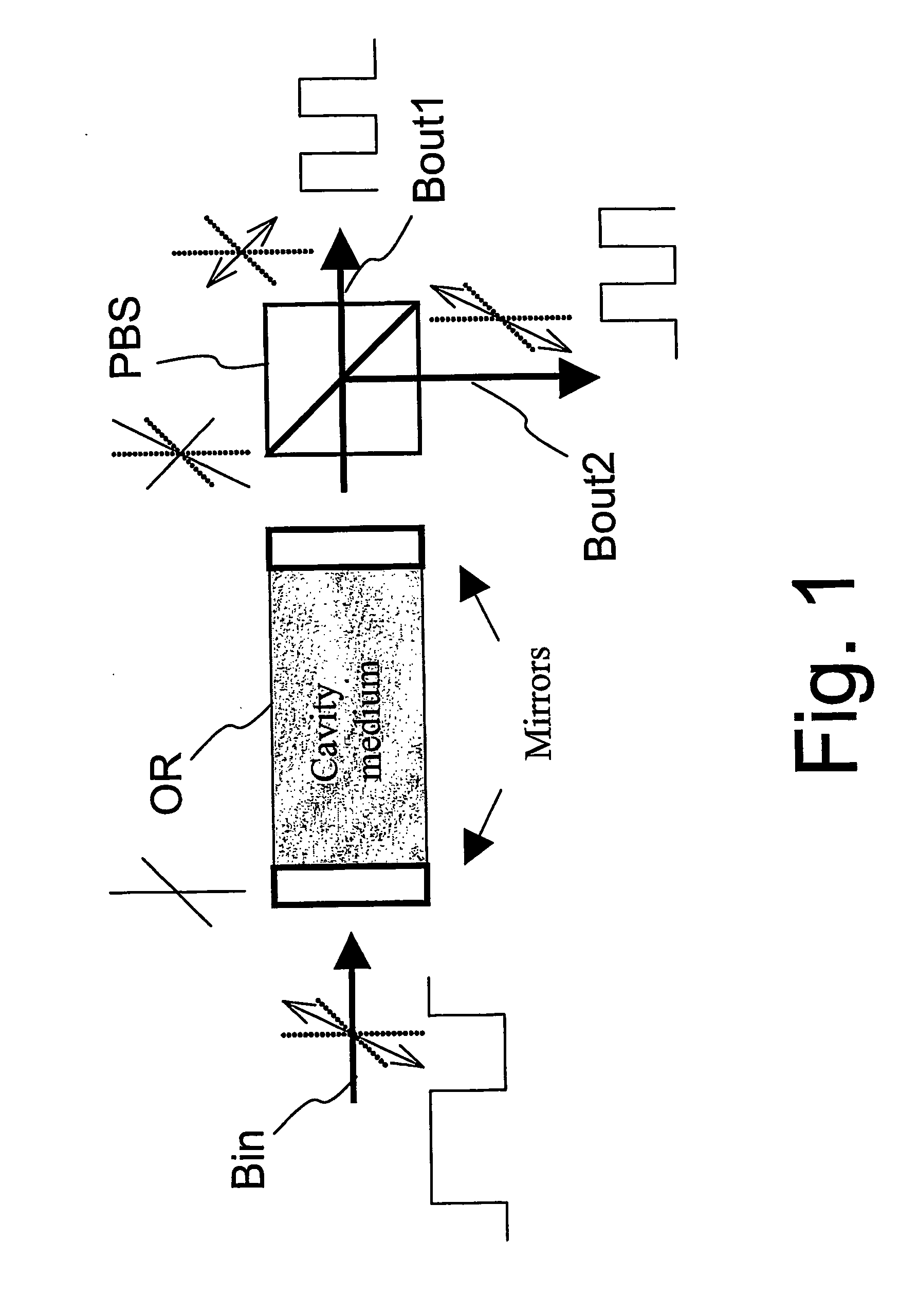
[0038] In the following the invention is mainly described referring to a birefringent resonator arrangement, where the matched and non-matched resonators are formed within a single physical cavity due to the birefringency. However, the invention is not limited to such embodiments, but the invention may also be realized using separate matched and non-matched resonators. One example of such an embodiment is later given in FIG. 19.

[0039] In the FIGS. 1,16,19 and 20 the polarization axes are depicted with “crossed” markings using both solid and dashed lines.

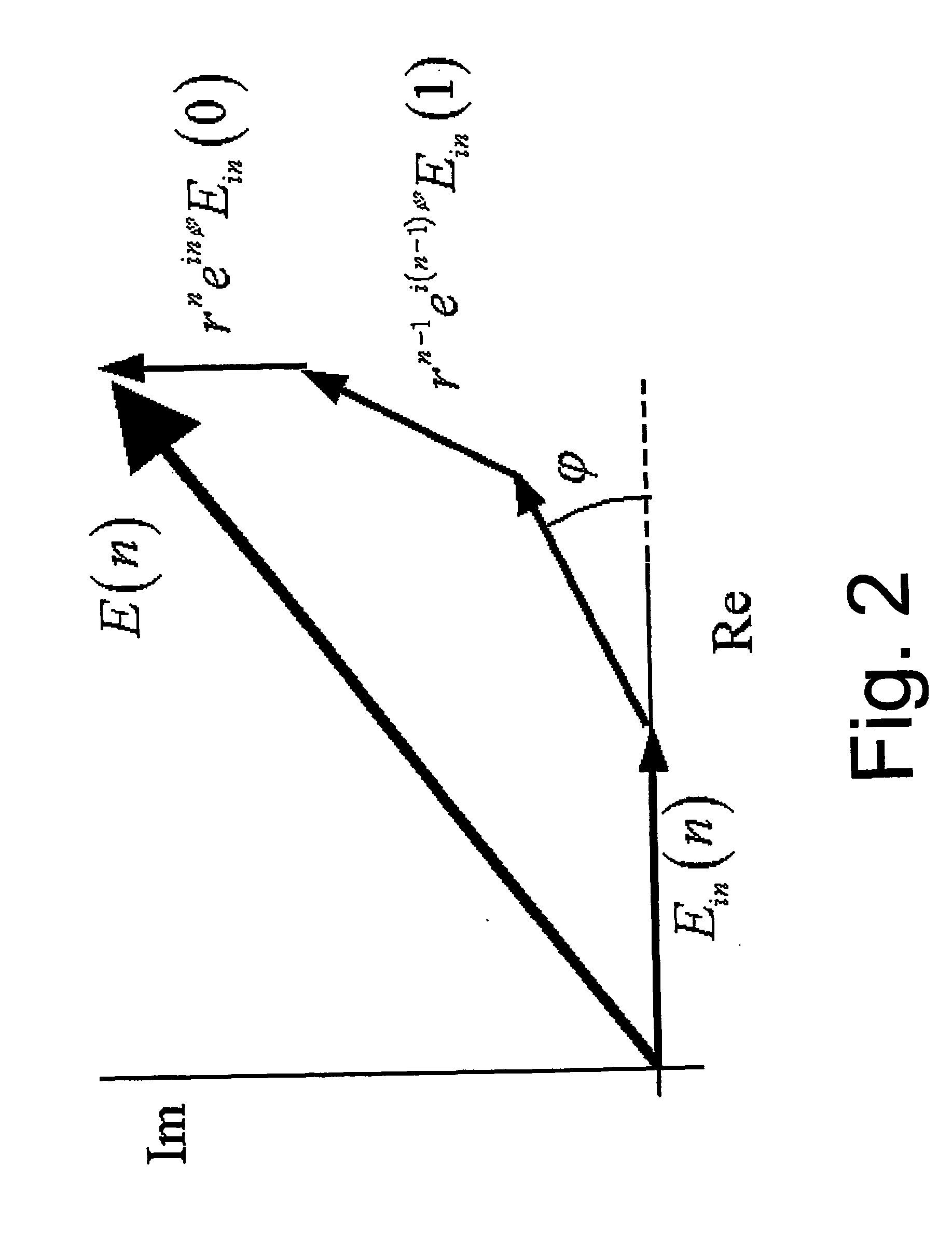
[0040] It is known from prior-art, as such, that an optical resonator behaves as an one-pole complex filter. Complex one-pole resonators generally, working either in optical, digital-electronic etc. domain, are able to transform purely real input signal to a complex one. Only when the wavelength of excitation is matched with the resonator, it has lowpass filtering function with no imaginary parts and therefore, it can directly be u...


PUM


Abstract

A method and an optical device in all-optical signal processing. It provides a novel way of taking into use the potential bandpass filtering capabilities of an optical complex one-pole resonator by, 1) excitating with at least part of the input signal an optical resonator arrangement that comprises two substantially parallel, independent, complex one-pole resonators arranged in a manner that one of the resonators is matched, and the other one is non-matched with the input signal, and 2) based on polarization separating further from the output of the optical resonator arrangement at least one optical output signal so that both the matched and non-matched resonators contribute to the formation of the output signal. The method and device can be utilized, for example, for optical signal analysis, optical clock recovery, or for producing high-frequency outputs from lower frequency input signals, like e.g. optical microwave generation.

Description

FIELD OF INVENTION [0001] The present invention relates to a method in optical signal processing and to an optical device for carrying out said method. More particularly, the invention relates to all-optical filters based on an optical resonator arrangement, which has a capacity to store temporally the electromagnetic energy of the incoming light and therefore has some memory about its past so that the filter can stay on a desired state for some time regardless of fast perturbations on the optical input signal. Such a filter may be referred to as a “slow” all-optical filter. The invention can be utilized, for example, for optical signal analysis, optical clock recovery, or for producing high-frequency outputs from lower frequency input signals, like e.g. optical microwave generation. DEFINITIONS [0002] The frequency of light is typically understood as the inverse of the wavelength of the electromagnetic field, i.e. ν=c / (nλ), where ν is the frequency, c is the speed of light in vacuu...

Claims


Application Information

Patent Timeline
Patent Type & Authority Applications(United States)
IPC IPC(8): G02B27/28G02B5/30H04B10/299H04B10/508H04J14/06H04L7/00
CPCH04B10/299H04L7/0075H04B10/508
Inventor VON LERBER, TUOMO
Owner LUXDYNE
Why Eureka
Try Eureka