Light-emitting diode lighting device

a technology of light-emitting diodes and lighting devices, which is applied in semiconductor devices for light sources, lighting applications, lighting and heating apparatus, etc., can solve the problems of inconvenient lighting, inconvenient lighting, and inability to meet the universal beam spread of conventional light sources, and achieves the effect of avoiding the formation of a single light-emitting diod

Active Publication Date: 2006-10-26
MCDERMOTT VERNON C +1
View PDF8 Cites 15 Cited by
  • Summary
  • Abstract
  • Description
  • Claims
  • Application Information

AI Technical Summary

Benefits of technology

[0008] It is therefore an object of the invention to provide a novel LED configuration that uses a minimum number of LED elements arranged in a space-saving configuration still effective to deliver a required light output.

Problems solved by technology

A drawback for traditional LEDs is their relatively wide beam spread that is most intense only in a small area, which is typically directed in a direction perpendicular to a plane on which the LED is mounted.
While progress has been made in creating LEDs with narrower, more focusable beam spreads, they still do not approach the universal beam spread possible with conventional light sources, such as incandescent or fluorescent light sources.
However, these configurations often have some drawback
making them undesirable.
Thus, increased size, excess heat output, and extra expense all become problems for device applicability, lifespan and marketability, respectively.

Method used


Image

  • Light-emitting diode lighting device
  • Light-emitting diode lighting device
  • Light-emitting diode lighting device

Examples


embodiment 200

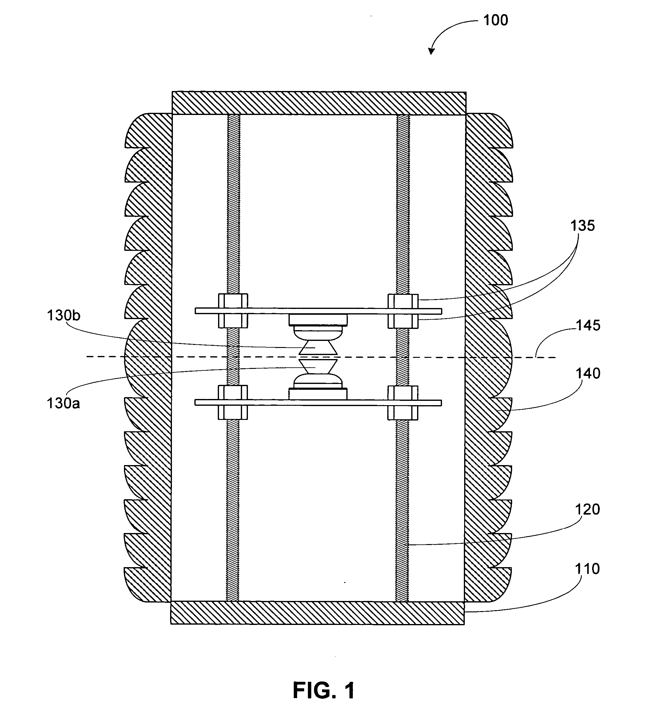
[0027]FIG. 2 illustrates an alternate embodiment 200 of a LED arrangement of the subject lighting device. In this embodiment, the LEDs are also arranged end-to-end, but in a manner that does not necessarily result in a complementary extension of beam spread, but may instead result in increased intensity of a center section 270 of the beam pattern, depending on the relative positioning of the LEDs 230. Also, depending on the specific beam pattern of the LEDs 230 used, the overall beam pattern of the combined unit 200 can be preselected. Arranged as shown in FIG. 2, a somewhat wider beam spread, directly from the LEDs 230, may be achieved, as compared with the orientation of LEDs in FIG. 1. Depending on the light output desirable for certain applications, the appropriate optical system can be utilized. Such optical systems, may include a filter or lens 240, including Fresnel or cylindrical Fresnel lenses, clear filter, opaque filters, refracting filters or the like.

[0028] In this embo...

embodiment 300

[0029]FIG. 3 illustrates an alternative embodiment 300 for supporting LEDs 330a, 330b in accordance with the invention. The overall configuration of the LEDs is similar to the embodiment of FIG. 1. However, in this embodiment, the upper LED 330a, is supported by the lower LED 330b, which is in-turn supported by support element 337. Naturally, the support element 337 could be secured directly to the upper LED 330a, and the lower LED 330b could be attached thereto. The LEDs 330 can be attached by adhesive, through solvent welding, by an intermediate mechanical connector or other satisfactory means. Naturally, to whichever LED 330a, 330b the support element 337 is mounted, it can be provided with linear adjustability, as described above.

[0030]FIG. 4 is a side, external view of a lighting device of the present invention. In this embodiment, a single cylindrical Fresnel lens 440 is supported by base 420. A LED unit 430 is provided inside the cylindrical Fresnel lens 440. In this embodime...


PUM


Abstract

A lighting device having one or more pair of side-emitting light-emitting diodes arranged end-to-end, one “flipped” relative to the other, such that the beam spreads of the LEDs complement one another and increase the overall beam spread of the device, or instead the intensity of the beam about a narrow angle.

Description

RELATED APPLICATION [0001] Priority in this application is claimed under 35 U.S.C. §119(e) to U.S. provisional application Ser. No. 60 / 674,206, filed Apr. 21, 2005, which is hereby incorporated by reference in its entirety.BACKGROUND OF THE INVENTION [0002] 1. Field of the Invention [0003] The present invention relates to a light-emitting diode configuration for lighting devices. Particularly, the present invention is directed to a lighting device utilizing the subject light-emitting diode configuration. [0004] 2. Description of Related Art [0005] A variety of methods and systems for utilizing light-emitting diodes (“LEDs”) for specialty lighting purposes have been developed. Generally, LEDs are used where low power consumption and / or long life are desirable. A drawback for traditional LEDs is their relatively wide beam spread that is most intense only in a small area, which is typically directed in a direction perpendicular to a plane on which the LED is mounted. While progress has...

Claims


Application Information

Patent Timeline
Patent Type & Authority Applications(United States)
IPC IPC(8): F21V5/00
CPCF21V5/045F21V5/046F21V14/02Y10S362/80F21Y2101/02F21W2111/04F21W2111/06F21Y2115/10F21V19/02
Inventor MCDERMOTT, VERNON C. SR.MCDERMOTT, VERNON JR.
Owner MCDERMOTT VERNON C
Why Eureka
Try Eureka