Active current sharing multiphase DC-DC converter

a technology of active current and converter, which is applied in the direction of electric variable regulation, process and machine control, instruments, etc., can solve the problems of delay in controller and relatively large board area

Active Publication Date: 2006-10-26
UNIV OF COLORADO THE REGENTS OF
View PDF4 Cites 90 Cited by
  • Summary
  • Abstract
  • Description
  • Claims
  • Application Information

AI Technical Summary

Benefits of technology

[0008] In one embodiment, a converter module for use as a phase in a multiphase DC-DC converter having a data bus for transferring current-sharing information is provided. The converter module comprises a power stage and a controller. The power stage comprises an input for receiving an input voltage and an output for providing an output voltage and an output current. The controller is coupled to the power stage to receive a feedback signal from the power stage. The controller further comprises a data bus port configured to receive the current-sharing information from the data bus and provide updated current-sharing information to the data bus. The controller is also configured to: (1) determine a current level being provided by said power stage, (2) update the current-sharing information based upon the determined current level, (3) determine a current error based upon the determined current level and the updated current-sharing information, (4) control an operation of said power stage based upon the current error, and (5) provide the updated current-sharing information to the data bus.

Problems solved by technology

This results in a delay in the controller while information is transferred and requires dedicated traces to each phase (resulting in a relatively large board area) and a communication protocol so that information can be through the phases or across a shared bus (e.g., a CAN bus, a daisy-chain, etc.).

Method used


Image

  • Active current sharing multiphase DC-DC converter
  • Active current sharing multiphase DC-DC converter
  • Active current sharing multiphase DC-DC converter

Examples


Embodiment Construction

Multiphase DC-DC Converter

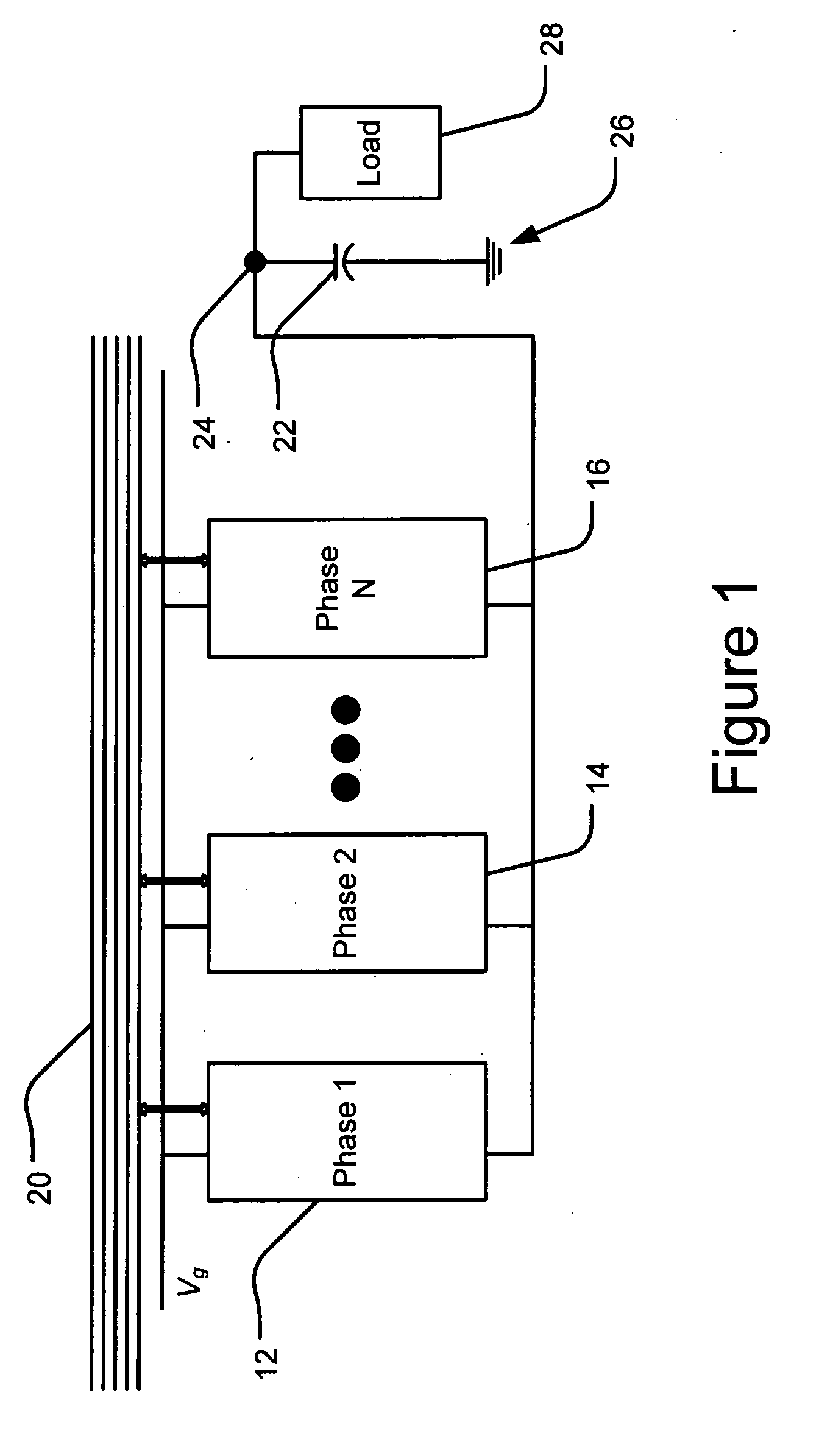
[0026]FIG. 1 shows a block diagram of an exemplary multiphase DC-DC converter 10 for controlling current sharing between multiple phases of the converter. In this embodiment, the converter 10 comprises N individual interleaved phases 12, 14, and 16, a digital bus 20, and an output capacitor 22 applied in parallel across a pair of output terminals 24 and 26 of the converter 10. The multiphase DC-DC converter 10 supplies a regulated output voltage Vout and an output current Iout to a load 28. The exemplary multiphase DC-DC converter 10 shown in FIG. 1 may comprise any number of two or more interleaved phases (i.e., N may comprise any positive integer greater than one).

[0027] Each of the individual interleaved phases 12, 14, and 16 comprises a power stage (e.g., a DC-DC converter), a digital controller, and analog-digital interface components (i.e., analog-to-digital (A / D) converters and / or digital-to-analog (D / A) converters). The digital controller, for ex...


PUM


Abstract

A converter module for use as a phase in a multiphase DC-DC converter having a data bus for transferring current-sharing information is provided. The converter module comprises a power stage and a controller. The power stage comprises an input for receiving an input voltage and an output for providing an output voltage and an output current. The controller is coupled to the power stage to receive a feedback signal from the power stage. The controller further comprises a data bus port configured to receive the current-sharing information from the data bus and provide updated current-sharing information to the data bus. The controller is also configured to: (1) determine a current level being provided by said power stage, (2) update the current-sharing information based upon the determined current level, (3) determine a current error based upon the determined current level and the updated current-sharing information, (4) control an operation of said power stage based upon the current error, and (5) provide the updated current-sharing information to the data bus. In another embodiment, a multiphase DC-DC power converter comprising a first phase, a second phase, and a data bus is provided. In yet another embodiment, a method of sharing current information between phases of a multiphase DC-DC converter is provided.

Description

CROSS-REFERENCE TO RELATED APPLICATIONS [0001] This application claims the benefit of U.S. provisional application No. 60 / 656,520 entitled “A masterless multiphase architecture for DC-DC converters with active current sharing” and filed by Regan Zane et al. on 25 Feb. 2005, which is hereby incorporated by reference as though fully set forth herein.BACKGROUND [0002] a. Field of the Invention [0003] The instant invention relates to active current sharing in a multiphase DC-DC converter. [0004] b. Background [0005] Power supplies for high performance microprocessors often must deliver low supply voltages with high currents while maintaining tight output voltage regulation in the presence of large load transients. Interleaved multiphase converters have been used in such systems due to advantages, such as lower switching frequencies for each phase, total current division among the phases, fast transient response, and use of smaller active and passive components. Multiphase converters, ho...

Claims


Application Information

Patent Timeline
Patent Type & Authority Applications(United States)
IPC IPC(8): H02J1/10
CPCH02M3/1584H02J1/102H02J1/106
Inventor ZANE, REGAN A.MAKSIMOVIC, DRAGANZHANG, YANG
Owner UNIV OF COLORADO THE REGENTS OF
Why Eureka
Try Eureka