Magnetically tapered air gap for electromagnetic transducer

a technology of electromagnetic transducers and air gaps, applied in the field of electromagnetic transducers, can solve problems such as counterproductive symmetry efforts

Inactive Publication Date: 2006-10-26
STILES ENRIQUE M +1
View PDF8 Cites 35 Cited by
  • Summary
  • Abstract
  • Description
  • Claims
  • Application Information

AI Technical Summary

Problems solved by technology

Applicant's observation is that these symmetry efforts can actually be counterproductive, and that a markedly asymmetrical m...

Method used


Image

  • Magnetically tapered air gap for electromagnetic transducer
  • Magnetically tapered air gap for electromagnetic transducer
  • Magnetically tapered air gap for electromagnetic transducer

Examples


Embodiment Construction

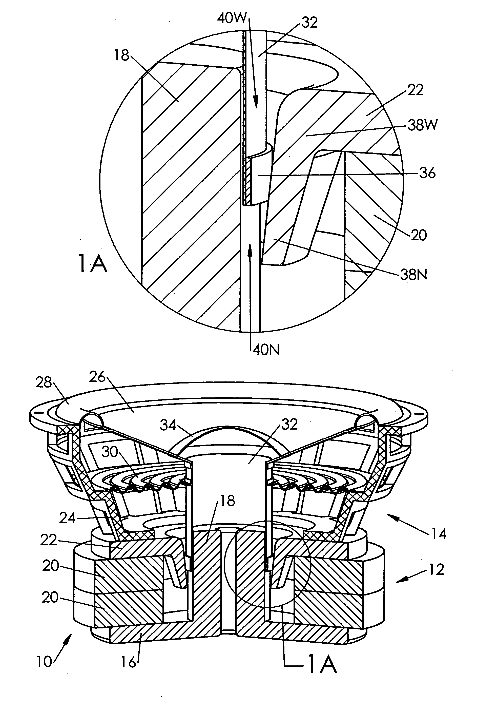
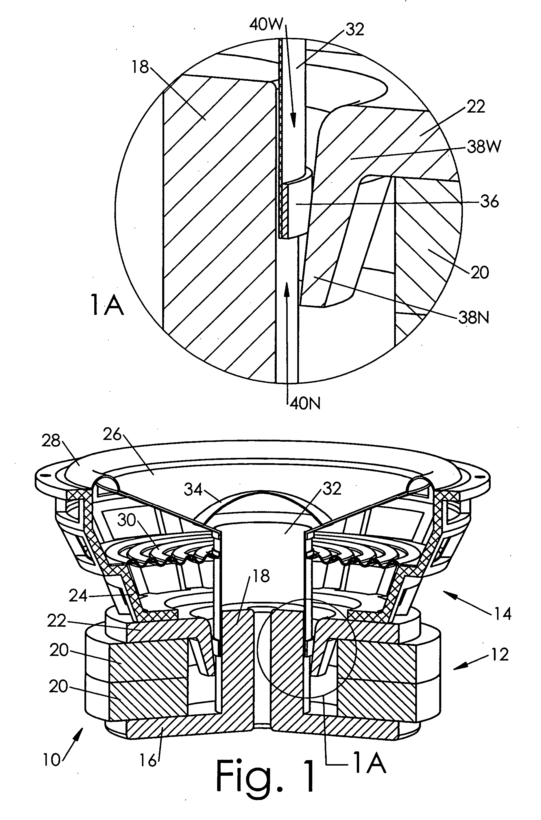
[0059] The invention will be understood more fully from the detailed description given below and from the accompanying drawings of embodiments of the invention which, however, should not be taken to limit the invention to the specific embodiments described, but are for explanation and understanding only.

[0060]FIG. 1 illustrates a loudspeaker 10 according to one embodiment of this invention. The loudspeaker includes a motor structure 12 coupled to a diaphragm assembly 14. The motor structure may have any suitable configuration, and is shown here as having an external magnet geometry. In this configuration, the motor structure includes a poleplate including a back plate 16 and a polepiece 18. One or more magnets 20 are magnetically coupled between the back plate and a top plate 22. The diaphragm assembly is coupled to the motor structure by a frame 24. A diaphragm or cone 26 is coupled to the frame by a flexible surround 28. A bobbin 32 is coupled to the diaphragm. A flexible spider ...


PUM


Abstract

An electromagnetic transducer, such as an audio loudspeaker, having an underhung voice coil disposed in a magnetically tapered air gap. The taper provides asymmetry in the magnetic flux field. As the voice coil moves in one direction, the motor becomes stronger and more efficient, and as the voice coil moves in the other direction, the motor becomes weaker and less efficient. This results in an increase in even-order harmonics. The magnetic taper may result from a geometric taper of one or both of the opposing steel pieces which form the gap, or it may result from one or both of them having an at least partially laminated structure. The geometric taper provides a magnetic reluctance gradient along the height of the magnetic air gap. The laminated structure provides a magnetic reluctance gradient through the thickness of the laminated member (e.g. top plate). The magnetic reluctance gradient produces a magnetic flux density gradient along the height of the magnetic air gap.

Description

RELATED APPLICATION [0001] This application is a continuation-in-part of application Ser. No. 11 / 114,737 “Semi-Radially-Charged Conical Magnet for Electromagnetic Transducer” filed Apr. 25, 2005 by Enrique M. Stiles. Both are commonly assigned to STEP Technologies, Inc.BACKGROUND OF THE INVENTION [0002] 1. Technical Field of the Invention [0003] This invention relates generally to electromagnetic transducers, and more specifically to the shape of the flux distribution within the magnetic air gap in a loudspeaker motor structure. [0004] 2. Background Art [0005] Conventional wisdom has been that it is desirable to provide as much symmetry as possible in the movement and force of the diaphragm assembly of a loudspeaker, to reduce distortion of the sound produced by variation in such characteristics. Loudspeaker designers have made significant efforts to ensure not only symmetric characteristics on either side of an at-rest center position, but also to ensure constant characteristics wi...

Claims


Application Information

Patent Timeline
IPC IPC(8): H04R9/06H04R11/02H04R1/00
CPCH04R9/025H04R2209/024H04R2209/022
Inventor STILES, ENRIQUE M.CALDERWOOD, RICHARD C.
Owner STILES ENRIQUE M
Why Eureka
Try Eureka