Grout sealer applicator device

Inactive Publication Date: 2006-10-26
CHEN LUNG CHIH
View PDF5 Cites 5 Cited by
  • Summary
  • Abstract
  • Description
  • Claims
  • Application Information

AI Technical Summary

Benefits of technology

[0008] The primary objective of the present invention is to provide a grout sealer applicator device including

Problems solved by technology

However, it will be difficult to control the pressing of the tubular body onto the sealer valve against the bias of the spring member, particularly when moving the applicator wheel along the ground.
For example, when a pressing force is applied onto the tubular body and thus onto the sealer valve against the bias of the spring member, the pressing force

Method used


Image

  • Grout sealer applicator device
  • Grout sealer applicator device
  • Grout sealer applicator device

Examples


Embodiment Construction

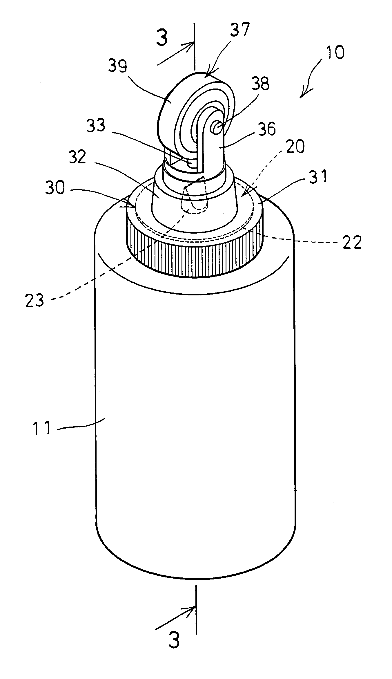
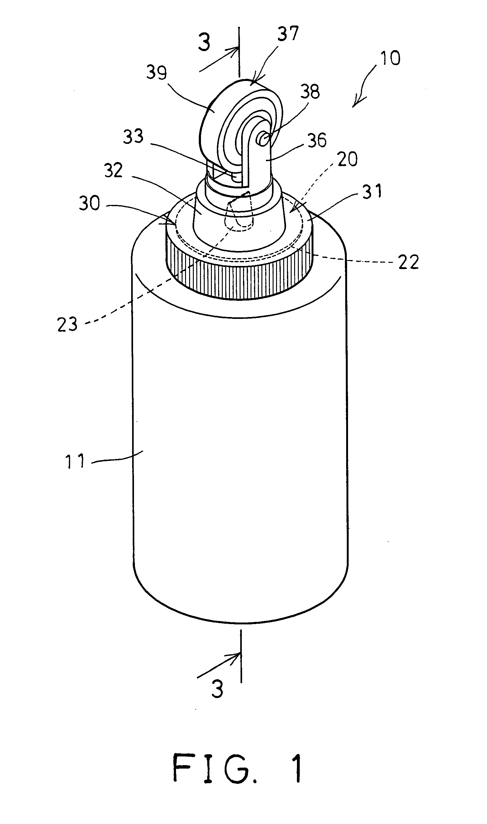
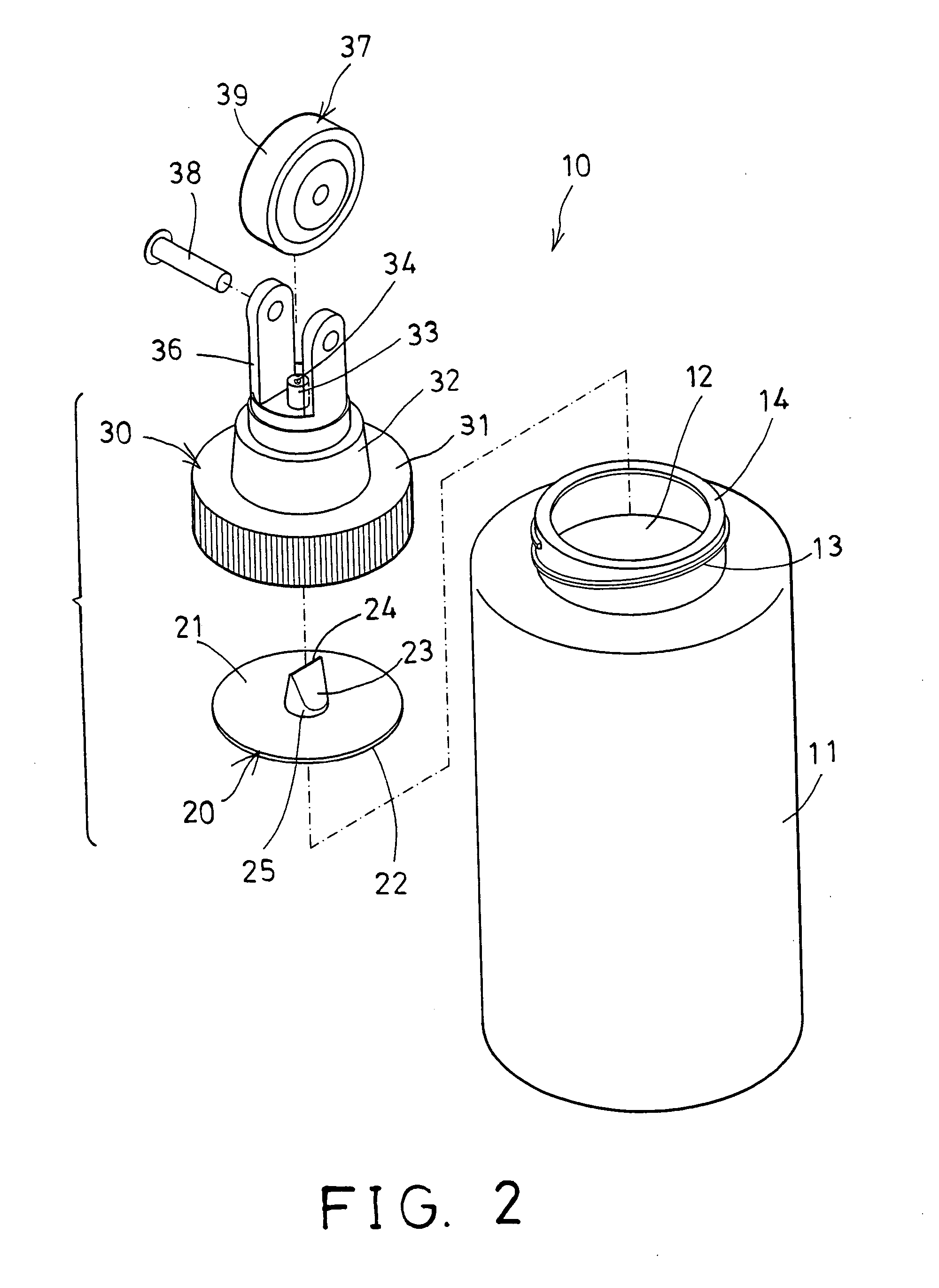
[0023] Referring to the drawings, and initially to FIGS. 1-3, a grout sealer applicator device 10 in accordance with the present invention comprises a container 11 including a chamber 12 provided or formed therein to define a sealer reservoir and to receive grout sealer material 90 therein (FIG. 5). The container 11 includes a mouth 13 provided or formed on top thereof, and having an upper peripheral surface 14 formed thereon.

[0024] A valve member 20 includes a panel 21 engageable onto the mouth 13 of the container 11, and having an outer peripheral flange 22 for engaging and seating onto the upper peripheral surface 14 of the mouth 13 of the container 11, and includes a nozzle 23 extended from the panel 21 and engageable into and communicating with the chamber 12 of the container 11 (FIGS. 4, 9), or extendible out of the container 11 (FIGS. 1, 3, 5 and 7-8).

[0025] The nozzle 23 of the valve member 20 includes a discharge aperture 24 formed therein (FIGS. 2-6), for discharging the...


PUM


Abstract

A grout sealer applicator device includes a container having a chamber to receive grout sealer material, a control ferrule attached onto a mouth of the container and having an outlet port for discharging the sealer material. A valve member is attached onto the mouth of the container, and includes a nozzle having a discharge aperture for selectively discharging the sealer material. A discharge wheel is rotatably attached to the control ferrule, and includes an outer peripheral surface facing toward the outlet orifice of the outlet port of the control ferrule, for receiving the grout sealer material from the outlet port, and thus for allowing the grout sealer material to be easily applied onto ground with the discharge wheel.

Description

BACKGROUND OF THE INVENTION [0001] 1. Field of the Invention [0002] The present invention relates to a grout sealer applicator device, and more particularly to a grout sealer applicator device having a sealer receiving and storing structure and an easily applying structure. [0003] 2. Description of the Prior Art [0004] Typical grout sealer applicator devices have been developed and provided for applying a liquid grout sealer onto ground or the like, and comprise an elongated tubular body defining a sealer reservoir, a sealer valve at an end of the tubular body, and a spring member biasing the sealer valve into a closed position and pressure activated by axial pressure on the tubular body into an open position against the bias of the spring member, and an applicator wheel carried by the sealer valve for receiving sealer from the reservoir through the sealer valve in the open position and for distributing sealer. [0005] For example, U.S. Pat. No. 6,386,782 to White, Sr. discloses one ...

Claims


Application Information

Patent Timeline
IPC IPC(8): B43M11/02
CPCB05C17/00513E04F21/165B05C17/10B05C17/00516B05C17/00596
Inventor CHEN, LUNG-CHIH
Owner CHEN LUNG CHIH
Why Eureka
Try Eureka