Leg press and abdominal crunch exercise machine
a leg press and exercise machine technology, applied in the field of exercise equipment and machines, can solve the problems of cumbersome linkage between the four bar linkage of the leg press and the resistance force used as a resistance force, not providing the most effective exercise results for users, and more difficult for users to start the exercis
- Summary
- Abstract
- Description
- Claims
- Application Information
AI Technical Summary
Benefits of technology
Problems solved by technology
Method used
Image
Examples
first embodiment
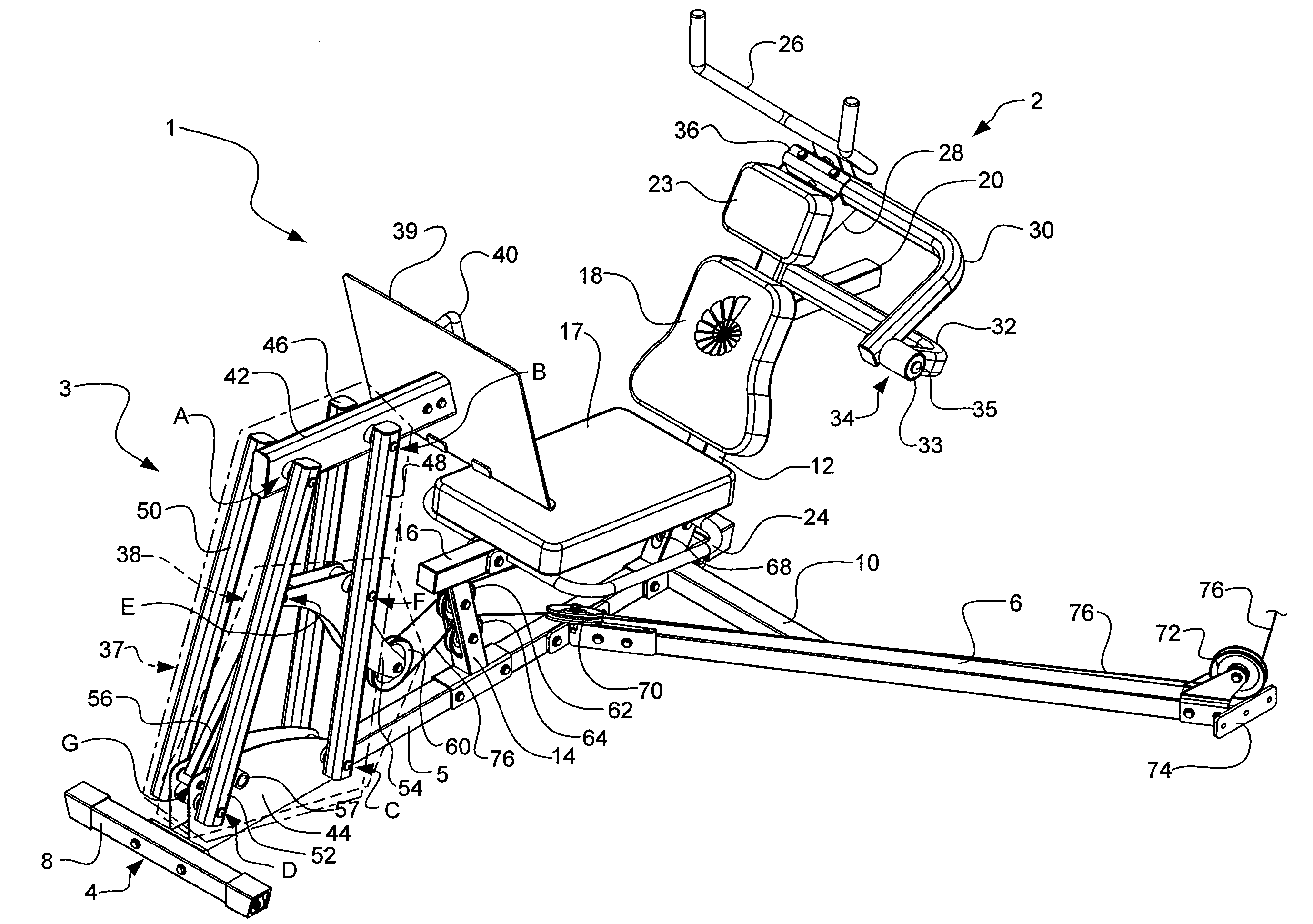
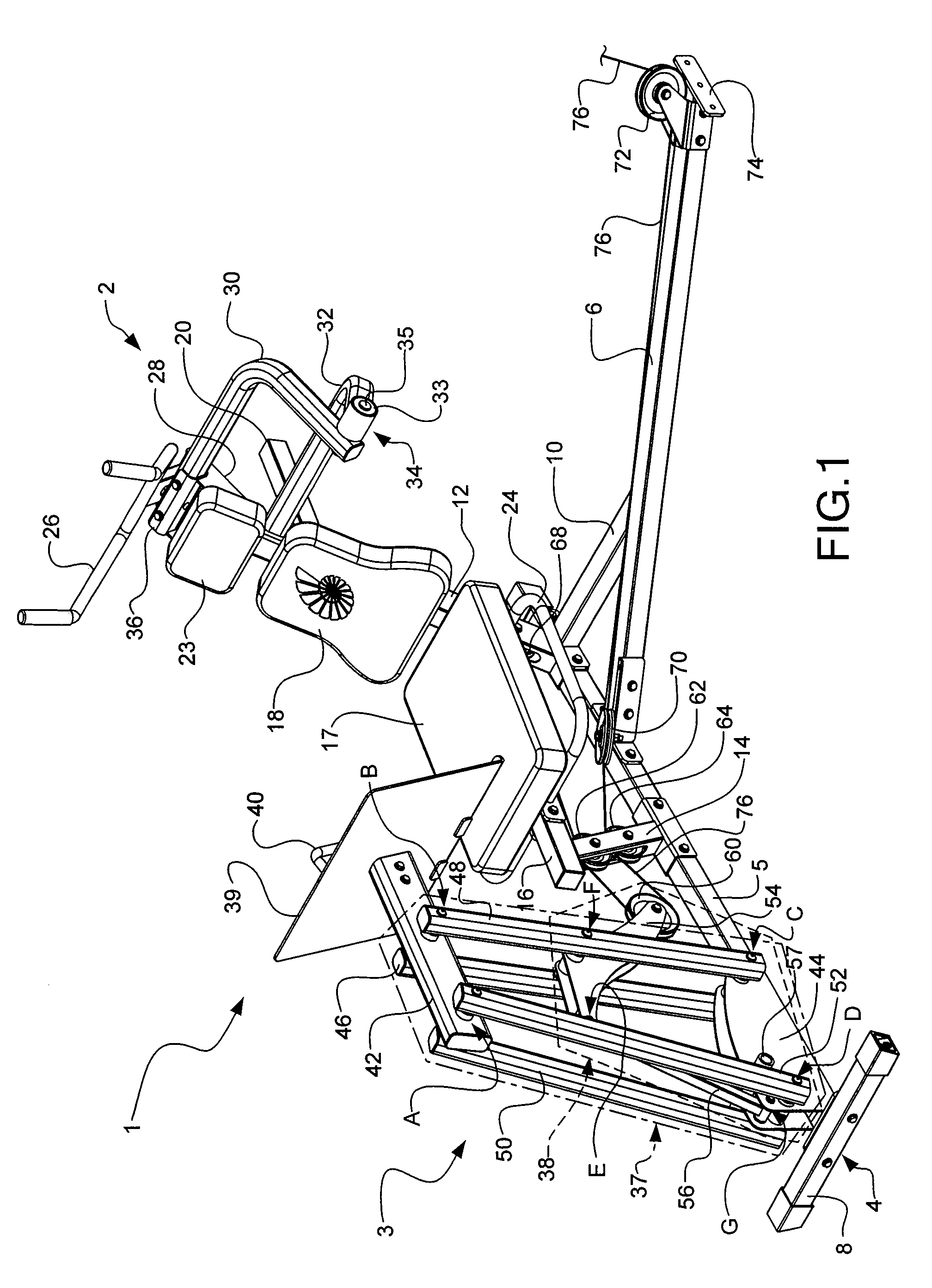
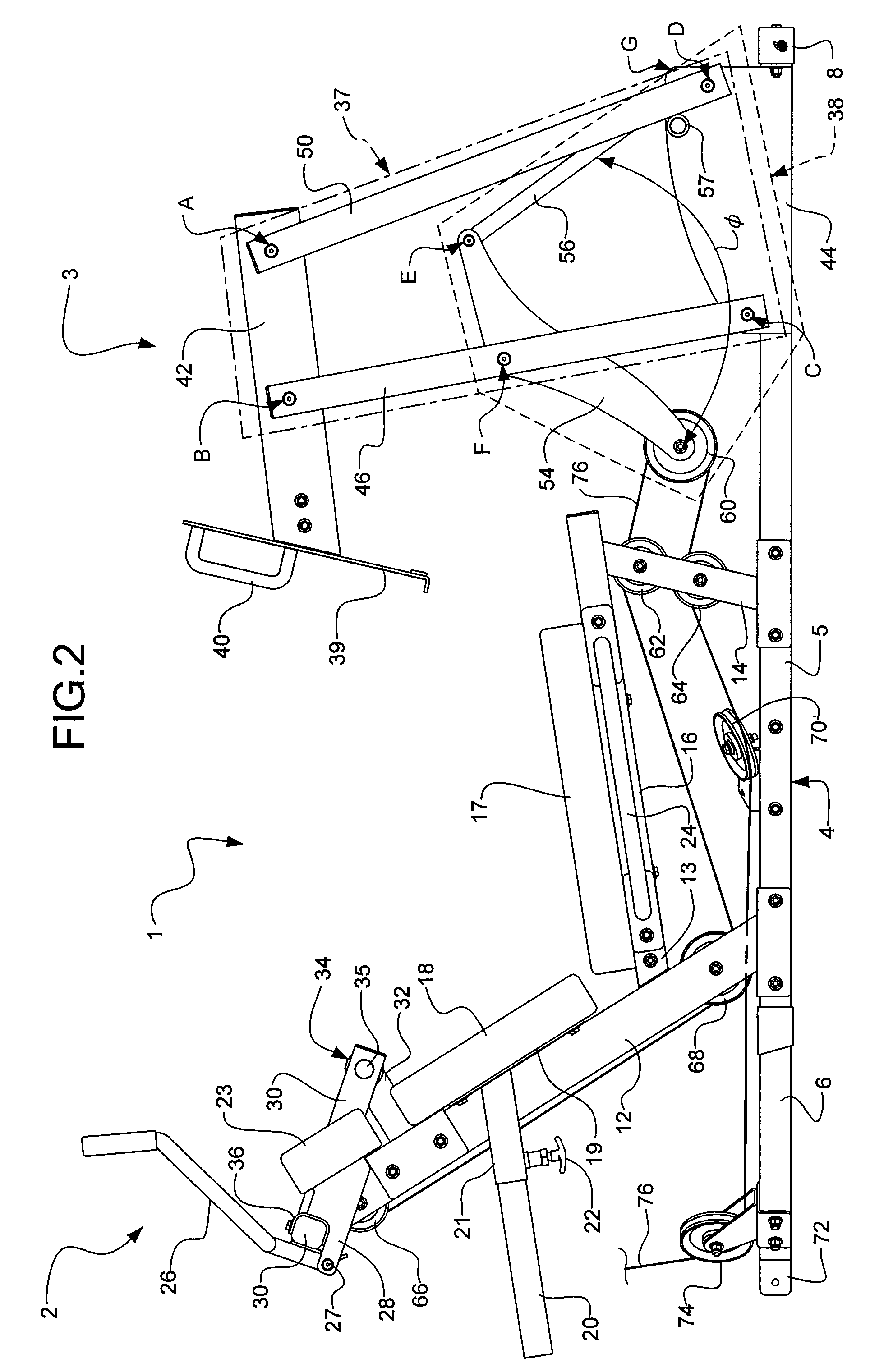
[0040] The leg press portion 3 of the exercise machine 1 is mounted on the frame 4 in front of the front seat post 14. The leg press portion 3 according to the exercise machine 1 is composed primarily of a first four bar linkage system 37, a second four bar linkage system 38, and a structure for engaging the feet or lower legs of the user, in this case, a foot plate 39. The first four bar linkage system 37 may be formed by two pairs of generally vertical bars: a left rear bar 46, a right rear bar 48, a left front bar 50, and a right front bar 52; a foot plate bar 42; and, in this exemplary embodiment, a riser frame 44. The left rear bar 46 and the right rear bar 48 may together be considered one of the four sides of the first four bar linkage system 37. In one exemplary embodiment, the left rear bar 46 and the right rear bar 48 may each be approximately 73.6 cm long between pivot point B and pivot point C. Similarly, the left front bar 50 and the right front bar 52 may together be c...
second embodiment
[0057] The top ends of the left rear bar 46, the right rear bar 48, the left front bar 50, and the right front bar 52 of the second embodiment may each be pivotally attached, generally transverse to the foot plate bar 42. The left front bar 50 and the right front bar 52 may be attached directly opposing each other on opposites sides of the foot plate bar 42 on an axel through the foot plate bar 42 at pivot point A. Likewise, the left rear bar 46 and the right rear bar 48 may be attached directly opposing each other on opposites sides of the foot plate bar 42 on an axel through the foot plate bar 42 at pivot point B. In the exemplary embodiment, the distance between pivot point A and pivot point B may be approximately 10.7 cm. The bottom ends of the left rear bar 46, the right rear bar 48, the left front bar 50, and the right front bar 52 may each be pivotally attached, generally transverse to a portion of the base rail 5. The left rear bar 46 and the right rear bar 48 may be attache...
third embodiment
[0069] the exercise machine 1 of the present invention is depicted in FIG. 19. This embodiment is configured for use, for example, with a circuit weight stack. The exercise machine 1 is built upon a frame 4. The frame 4 is composed of several sections, including a base rail 5, a handlebar post attachment rail (not shown), a handlebar support post 7, a rear support post 11, a rear support plate 9, a rear seat post 12, a front seat post 14, and a seat bar 16. The various bars and post that compose the frame 4 may be, for example, straight, tubular (e.g., round or square), metal (e.g., steel) beams that are attached together, for example, with brackets and through bolts. Such brackets may be separate pieces or integral with the various bars and posts.
[0070] The base rail 5 is the foundation of the frame 4 and generally rests flat upon a floor surface. The base rail 5 generally extends generally the length of the exercise machine 1 as shown in FIG. 19. This embodiment of the exercise ma...
PUM
 Abstract
Description
Claims
Application Information
 - R&D
- Intellectual Property
- Life Sciences
- Materials
- Tech Scout
- Unparalleled Data Quality
- Higher Quality Content
- 60% Fewer Hallucinations
Browse by: Latest US Patents, China's latest patents, Technical Efficacy Thesaurus, Application Domain, Technology Topic, Popular Technical Reports.
© 2025 PatSnap. All rights reserved.Legal|Privacy policy|Modern Slavery Act Transparency Statement|Sitemap|About US| Contact US: help@patsnap.com


