Electrophysiology loop catheter

Inactive Publication Date: 2006-10-26
BOSTON SCI SCIMED INC
View PDF61 Cites 164 Cited by
  • Summary
  • Abstract
  • Description
  • Claims
  • Application Information

AI Technical Summary

Benefits of technology

[0014] Another embodiment of the invention is directed to an electrophysiology catheter comprising a handle having a distal end and a proximal end, the handle including an actuator, a flexible shaft having a proximal end and a distal end and a longitudinal axis that extends along a length of the shaft, the proximal end of the shaft being attached to the distal end of the handle, a tip assembly having a proximal end and a distal end, the proximal end of the tip assembly being attached to the distal end of the shaft and the tip assembly including an adhesive cured in a configuration to support the tip assembly in a first orientation including a bend at the proximal end of the tip assembly having a first angle of approximately ninety degrees relative to the longitudinal axis of the shaft, a first cable, attached to the actuator and the tip assembly, that extends through the shaft, the first cable being adapted to change an orientation of the tip asse

Problems solved by technology

The human heart is a very complex organ, which relies on both muscle contraction and electrical impulses to function properly.
In some individuals, the electrical impulses of the heart develop an irregular propagation, disrupting the heart's normal pumping action.
Though mapping and ablation of these triggers appears to be curative in patients with paroxysmal atrial fibrillation, there are a number of limitations to ablating focal triggers via mapping and ablating the earliest site of activation with a “point” radiofrequency lesion.
Such a technique is relatively involved, and requires significant skill and attention from the clinician performing the procedures.

Method used


Image

  • Electrophysiology loop catheter
  • Electrophysiology loop catheter
  • Electrophysiology loop catheter

Examples


Embodiment Construction

[0103] In this description, various aspects and features of the present invention will be described. One skilled in the art will appreciate that the features may be selectively combined in a device depending on the particular application. Furthermore, any of the various features may be incorporated in a catheter and associated method of use for mapping and / or ablation procedures.

Catheter Overview

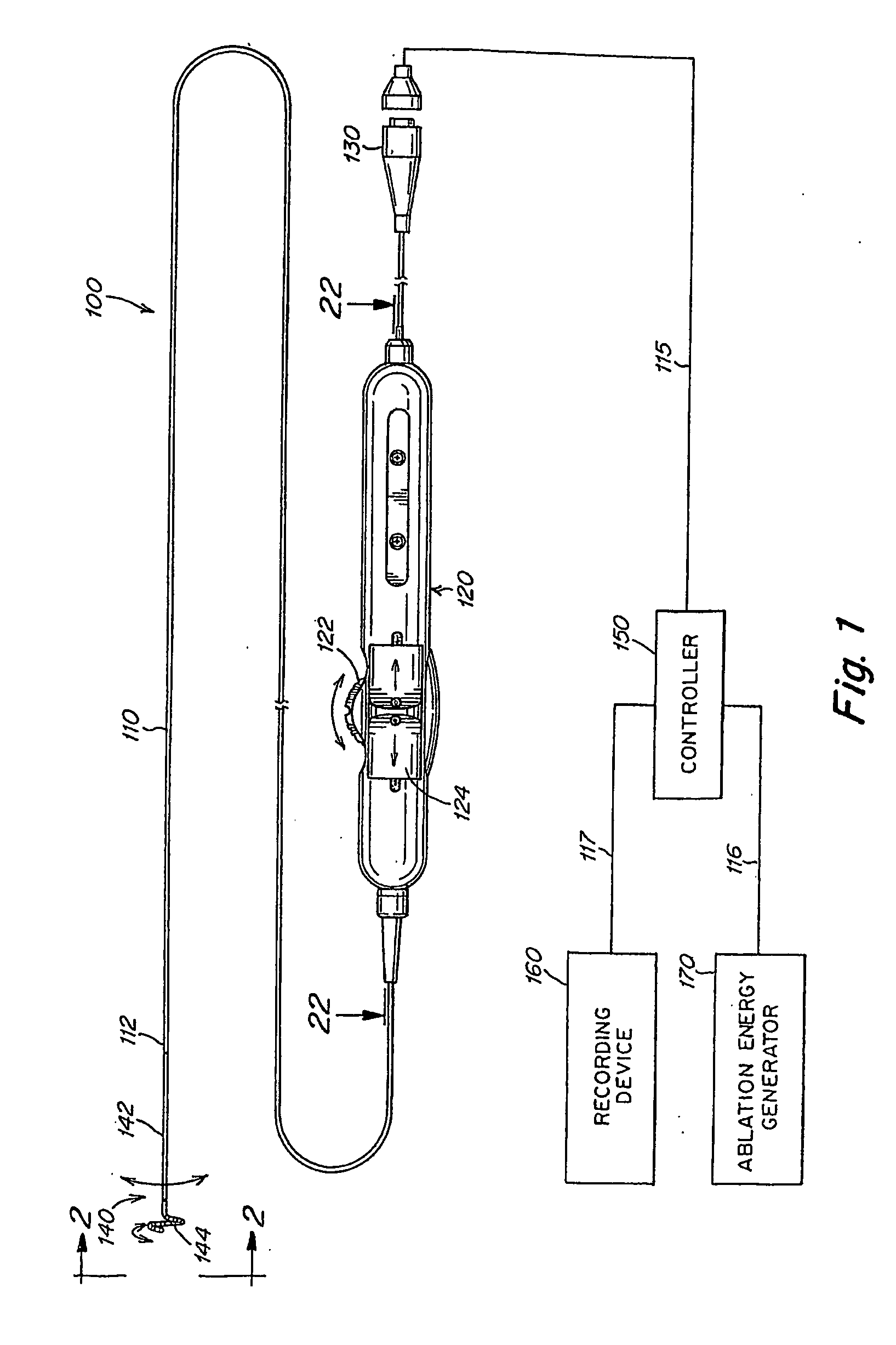
[0104] Reference is now made to FIG. 1, which illustrates an overview of a mapping and / or ablation catheter system for use in electrophysiology procedures, in accordance with the present invention. The system includes a catheter 100 having a flexible shaft 110, a control handle 120, and a connector 130. When used in mapping applications, the connector 130 is used to allow signal wires running from mapping electrodes at a distal end of the catheter 100 to be connected to a device for recording signals, such as a recording device 160. When used in ablation applications, connector 130 is use...


PUM


Abstract

An electrophysiology catheter including control, localization, and / or fluid delivery features, and methods of using the same. One embodiment of the invention is directed to an electrophysiology catheter including a superelastic wire and a cable, and a method of controlling the catheter using the cable. Another embodiment is directed to an electrophysiology catheter including an adhesive to bias the orientation of the catheter. A further embodiment is directed to an electrophysiology catheter including adhesive and one or more cables, and a method of controlling the catheter using the one or more cables. Another embodiment is directed to a method including acts of injecting a fluid into the heart of a patient and adjusting the diameter of an arcuate curve of the catheter. Further embodiments are directed to a catheter having multiple position sensors on an arcuate curve of the catheter, or a position sensor associated with a movable electrode of the catheter.

Description

BACKGROUND OF THE INVENTION [0001] 1. Field of the Invention [0002] The present invention relates to electrophysiology catheters, and more particularly to electrophysiology catheters for performing endocardial mapping and / or ablation procedures. [0003] 2. Discussion of the Related Art [0004] The human heart is a very complex organ, which relies on both muscle contraction and electrical impulses to function properly. The electrical impulses travel through the heart walls, first through the atria and then the ventricles, causing the corresponding muscle tissue in the atria and ventricles to contract. Thus, the atria contract first, followed by the ventricles. This order is essential for proper functioning of the heart. [0005] In some individuals, the electrical impulses of the heart develop an irregular propagation, disrupting the heart's normal pumping action. The abnormal heartbeat rhythm is termed a “cardiac arrhythmia.” Arrhythmias may occur when a site other than the sinoatrial n...

Claims


Application Information

Patent Timeline
IPC IPC(8): A61B5/04A61B18/14A61B5/296
CPCA61B5/0422A61B5/6856A61B18/1492A61B18/1815A61B2018/1467A61B2018/00375A61B2018/1286A61B2018/1407A61B2018/1435A61B2018/00273A61B5/287A61B2018/00791
Inventor FALWELL, GARYMACADAM, DAVIDPKUONG, DARANY
Owner BOSTON SCI SCIMED INC
Why Eureka
Try Eureka