Method and system to correct motion blur in time-of-flight sensor systems

a sensor system and motion blur technology, applied in the field of camera or range sensor systems, can solve problems such as inaccurate final depth images

Inactive Publication Date: 2006-10-26
CANESTA
View PDF4 Cites 43 Cited by
  • Summary
  • Abstract
  • Description
  • Claims
  • Application Information

AI Technical Summary

Problems solved by technology

However such systems may erroneously yield the same measurement information for a distant target object that happens to have a shiny surface and is thus highly reflective, as for a target obj

Method used


Image

  • Method and system to correct motion blur in time-of-flight sensor systems
  • Method and system to correct motion blur in time-of-flight sensor systems
  • Method and system to correct motion blur in time-of-flight sensor systems

Examples


Embodiment Construction

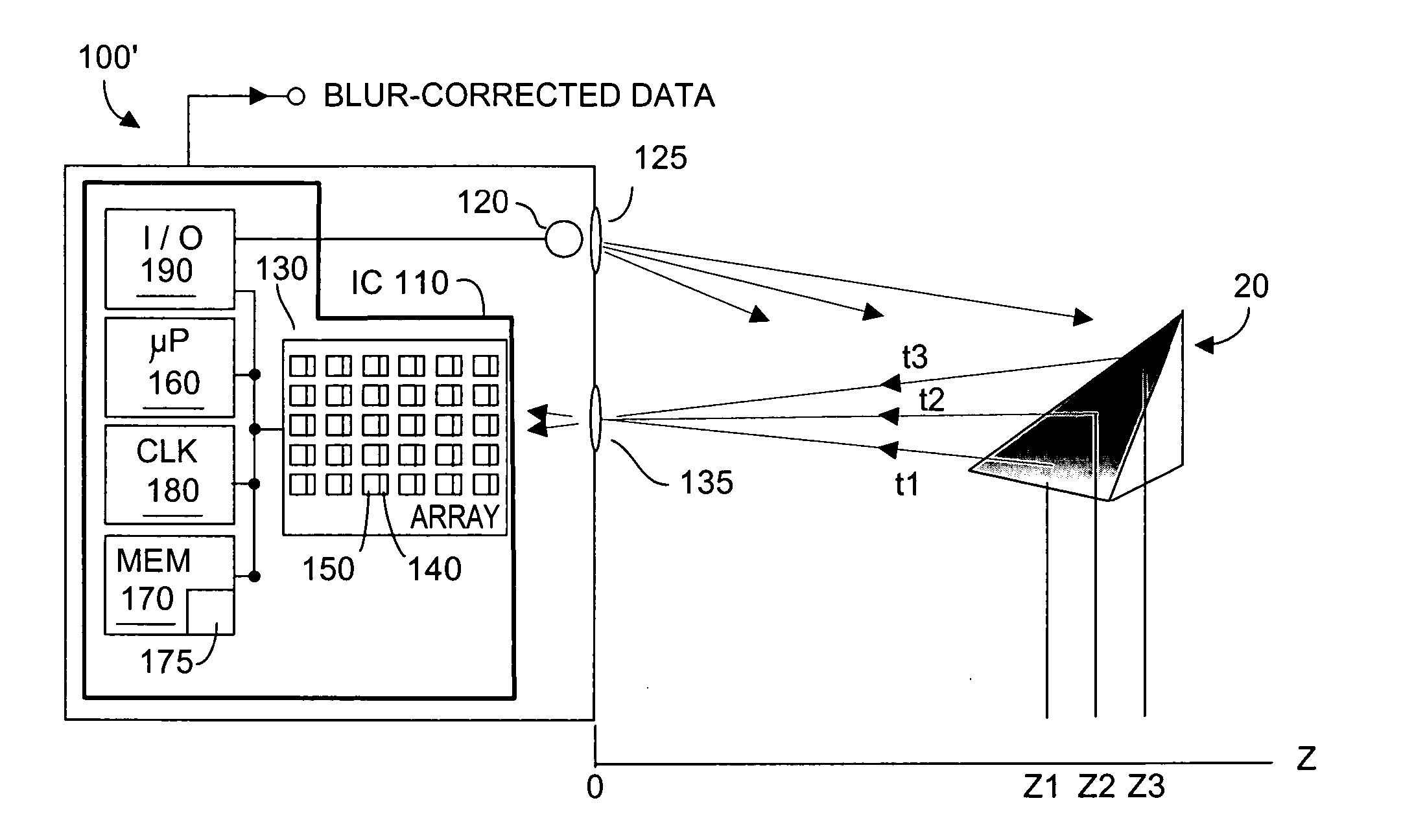
[0021]FIG. 3 depicts a system 100′ that includes a software routine or algorithm 175 preferably stored in a portion of system memory 170 to implement the present invention. Routine 175 may, but need not be, executed by system microprocessor 160 to carryout the method steps depicted in FIG. 4, namely to detect and compensate for relative motion error in depth images acquired by system 100′, to yield corrected distance data that is de-blurred with respect to such error.

[0022] As noted, it usually is advantageous to obtain multiple data measurements using a TOF system 100′. Thus, microprocessor 160 may program via input / output system 190 optical energy emitter 120 to emit energy at different initial phases, for example to make system 100′ more robust and more invariant to reflectivity of objects in scene 20, or to ambient light level effects in the scene. If desired, the length (exposure) and / or frequency of the emitter optical energy can also be programmed and varied. Each one of the...


PUM


Abstract

A method and system corrects motion blur in time-of-flight (TOF) image data in which acquired consecutive images may evidence relative motion between the TOF system and the imaged object or scene. Motion is deemed global if associated with movement of the TOF sensor system, and motion is deemed local if associated with movement in the target or scene being imaged. Acquired images are subjected to global and then to local normalization, after which coarse motion detection is applied. Correction is made to any detected global motion, and then to any detected local motion. Corrective compensation results in distance measurements that are substantially free of error due to motion-blur.

Description

RELATION TO PENDING APPLICATIONS [0001] Priority is claimed to co-pending U.S. provisional patent application Ser. No. 60 / 650,919 filed 8 Feb. 2005, entitled “A Method for Removing the Motion Blur of Time of Flight Sensors”.FIELD OF THE INVENTION [0002] The invention relates generally to camera or range sensor systems including time-of-flight (TOF) sensor systems, and more particularly to correcting errors in measured TOF distance (motion blur) resulting from relative motion between the system sensor and the target object or scene being imaged by the system. BACKGROUND OF THE INVENTION [0003] Electronic camera and range sensor systems that provide a measure of distance from the system to a target object are known in the art. Many such systems approximate the range to the target object based upon luminosity or brightness information obtained from the target object. However such systems may erroneously yield the same measurement information for a distant target object that happens to ...

Claims


Application Information

Patent Timeline
IPC IPC(8): A61B5/05
CPCG01S17/89G01S7/497
Inventor RAFII, ABBASGOKTURK, SALIH BURAK
Owner CANESTA
Why Eureka
Try Eureka