Method for determining the position of an instrument with an x-ray system

a technology of x-ray system and position determination, which is applied in the field of determining the position of an instrument with an x-ray system, can solve the problems of time-consuming change, difficult control of this type of instrument, and inability to determine the position of the instrument in two dimensions, etc., and achieves the effect of less complicated and flexible us

Active Publication Date: 2006-10-26
SIEMENS HEALTHCARE GMBH
View PDF8 Cites 29 Cited by
  • Summary
  • Abstract
  • Description
  • Claims
  • Application Information

AI Technical Summary

Benefits of technology

[0017] The present method thus makes it possible to determine the 3D position of an instrument or a location of the instrument in a structure of an object with a simple monoplanar x-ray system. Monoplanar x-ray systems have the advantage of being less complicated and more flexible to use than for example biplanar x-ray systems. They are also able to be combined with magnetic navigation for example.
[0018] By contrast with localization systems which are not based on x-ray imaging, for example those using optical or electromagnetic sensors, determining the 3D position with an x-ray system has the advantage that no new instruments are required and all instruments able to be shown in x-ray images can be localized. In addition the positions of a large number of different locations of an instrument or a large number of different instruments can be localized in three dimensions with the present method.

Problems solved by technology

Controlling this type of instrument can sometimes be very demanding, especially if the blood vessels are very damaged and have many branches.
When a monoplanar x-ray system is used however, the position of the instruments can only be determined in two dimensions.
This demands either the use of an expensive biplanar x-ray system or a time-consuming change in the angulation of a monoplanar x-ray system in conjunction with a sequential recording of two x-ray images from different directions.
A disadvantage of this method compared to x-ray imaging lies in the fact that only instruments equipped with specific sensors can be localized.
Furthermore the number of instruments able to be localized as well as the number of sensors per instrument is restricted with these types of localization systems.

Method used


Image

  • Method for determining the position of an instrument with an x-ray system
  • Method for determining the position of an instrument with an x-ray system
  • Method for determining the position of an instrument with an x-ray system

Examples


Embodiment Construction

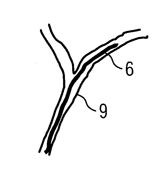
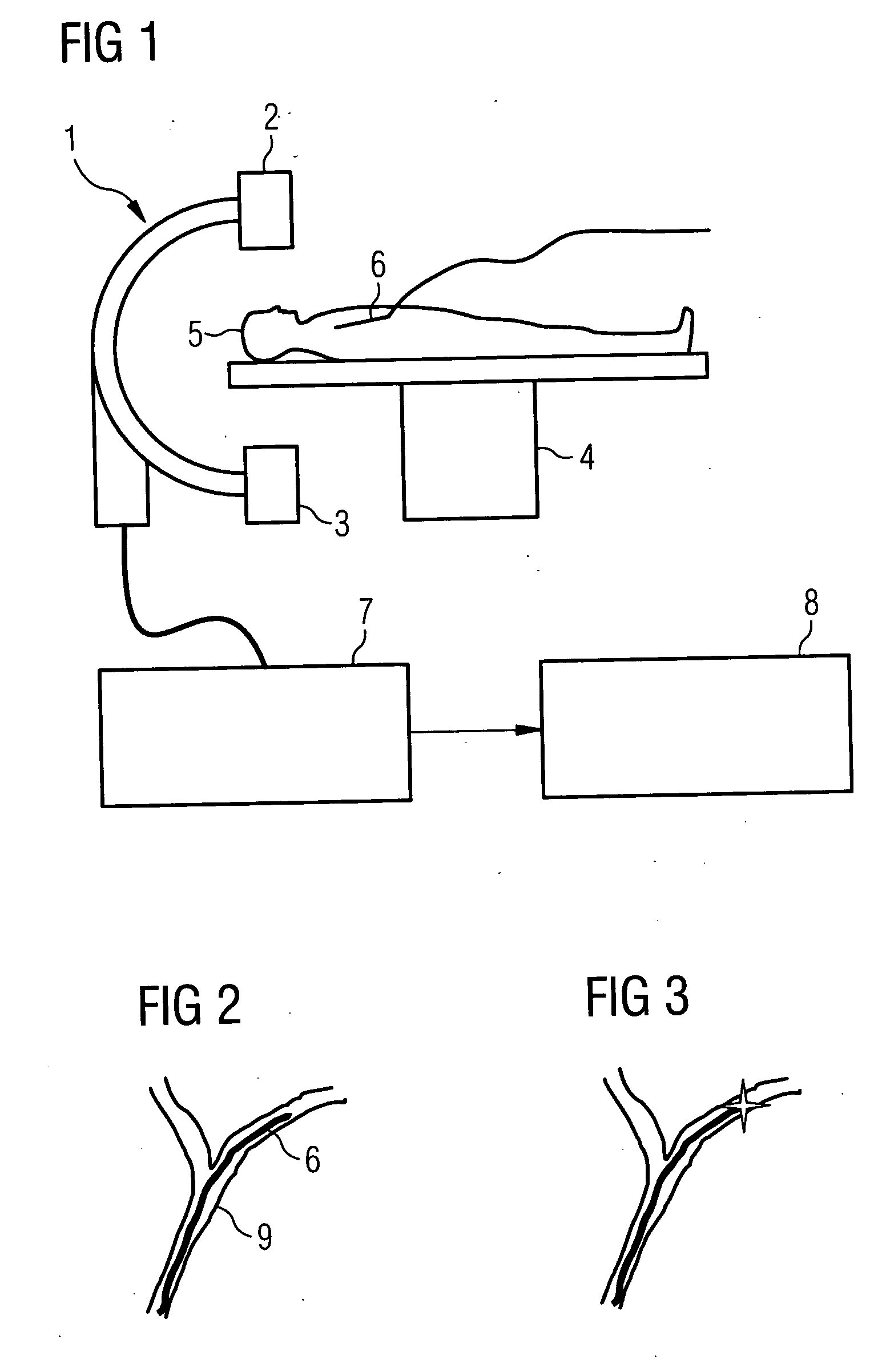
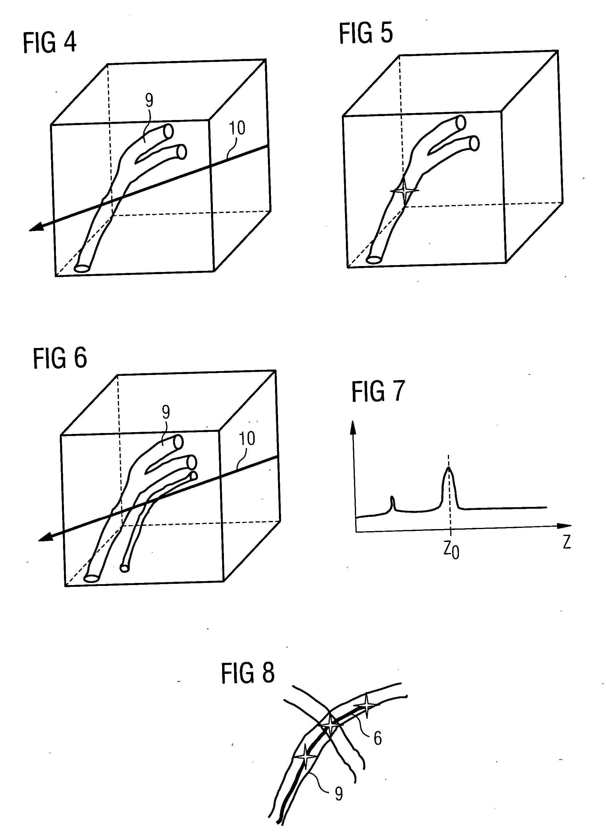
[0027] The present example is designed to illustrate the monitoring of the guidance of a catheter in blood vessels of the patient in accordance with the present method. This type of catheter is restricted to vessel interventions in the area of blood vessels. In such a case for example 3D image data can be provided from a 3D angiography image of the patient.

[0028] This 3D image data record can in this case be recorded either before the introduction of the catheter or also after the introduction of the catheter directly before the first 3D position is determined. When an image is recorded after the introduction of the catheter, an x-ray system is required which makes it possible to record such a data record using 3D rotation angiography for example. In other cases the imaging modality for the recording of the 3D image data record can be completely independent of the x-ray system used for the intervention. The 3D image data record recorded is registered with the x-ray system used. In ...


PUM


Abstract

The present invention relates to a method for determining the position of an instrument in a structure of an object with an x-ray system, in which a 3D image data record is provided for at least one area of the object relevant for determining the position, the x-ray system is registered with the 3D image data record, after the introduction of the instrument into the structure at least one 2D x-ray image of the relevant area is recorded from at least one direction of projection with a known projection geometry with the x-ray system and a 2D position of a first location of the instrument is recorded in the 2D x-ray image. In the method a projection line in accordance with the known projection geometry is placed through the 3D image data record at the 2D position and a 3D position of the first location of the instrument in the 3D image data record is determined from an intersection of the projection line with the structure. The method enables the 3D position to be determined with a simple monoplanar x-ray system.

Description

CROSS REFERENCE TO RELATED APPLICATION [0001] This application claims priority of the German application No. 10 2005 007 893.1 DE filed Feb. 21, 2005, which is incorporated by reference herein in its entirety. FIELD OF THE INVENTION [0002] The present invention relates to a method for determining the position of an instrument in a structure of an object, especially in a hollow canal or a hollow organ, with an x-ray system, in which a first 3D image data record is provided for at least one area of the object relevant for determining the position, the x-ray system is registered with the first 3D image data record, after the introduction of the instrument into the structure at least one 2D x-ray image of the relevant area is recorded from at least one direction of projection with a known projection geometry with the x-ray system, and a 2D position of a first location of the instrument is recorded in the 2D x-ray image. BACKGROUND OF THE INVENTION [0003] Interventional or surgical proce...

Claims


Application Information

Patent Timeline
Patent Type & Authority Applications(United States)
IPC IPC(8): A61B6/00
CPCA61B6/12A61B6/4441A61B6/466A61B6/504A61B19/52A61B19/5225G06T2210/41A61B2019/505A61B2019/5238A61B2019/5265A61B2019/5289G06T19/00A61B19/5244A61B34/20A61B90/36A61B90/37A61B2034/105A61B2034/2065A61B2090/364A61B2090/376
Inventor BOESE, JANKLEEN, MARTINRAHN, NORBERT
Owner SIEMENS HEALTHCARE GMBH
Why Eureka
Try Eureka