Waveform sensing and regulating fluid flow valve

a waveform sensing and fluid flow technology, applied in the field of hydrocephalus treatment, can solve the problems of inability to accurately control the flow of fluid, and inability to use mechanisms in real situations, so as to achieve the effect of precise control of the flow and easy control of the volume and rate of fluid transpor

Inactive Publication Date: 2006-10-26
CHILDRENS MEDICAL CENT CORP +1
View PDF27 Cites 15 Cited by
  • Summary
  • Abstract
  • Description
  • Claims
  • Application Information

AI Technical Summary

Benefits of technology

[0009] The oscillating valve elements of the present invention are able to provide a fast response to variations in the CSF flow dynamic parameters. An impedance sensor monitors the impedance values of all oscillating valve element's and provides feedback signals to the controller. Impedance changes caused by valve clogging or perturbations in the CSF pulsations are monitored, and a feedback signal from the impedance controller to the processor triggers a corrective response.
[0014] In this aspect, the present invention differs from conventional shunt valves which rely, for the most part, on a threshold pressure differential to open (and in some instances an maximum pressure differential for operation to prevent over drainage due to siphoning effects). In contrast to these static designs, the shunt valves and valve arrays of the present invention permit more precise control over the fluid transport. By controlling the number of valves operational at any given time and / or the oscillation of their deflectable gate elements, the volume and rate of fluid transport can be readily controlled without resort to fixed threshold or maximum pressure parameters. Thus, the present invention permits essentially pressure independent control of cerebrospinal fluid transport, limited only by CSF pulsation and the elastic modulus of the deflectable gate.

Problems solved by technology

This accumulation of fluid increases the pressure within the ventricles and without medical intervention can cause brain damage and / or death to the patient.
However, there are a number of problems associated with these shunts, for example, the control of the CSF flow typically is limited to a preset pressure.
Although some shunt valves have mechanisms to adjust the pressure difference that triggers the valve to open, such mechanisms are typically cumbersome to use in real situations.
In addition, the valves become clogged over time.
Moreover, the existing shunts do not take into consideration the effects associated with CSF pulsations.
Under-drainage or over-drainage may arise due to the mismatched dynamic characteristics of the valve of the shunt and the CSF pulsations.

Method used


Image

  • Waveform sensing and regulating fluid flow valve
  • Waveform sensing and regulating fluid flow valve
  • Waveform sensing and regulating fluid flow valve

Examples


Embodiment Construction

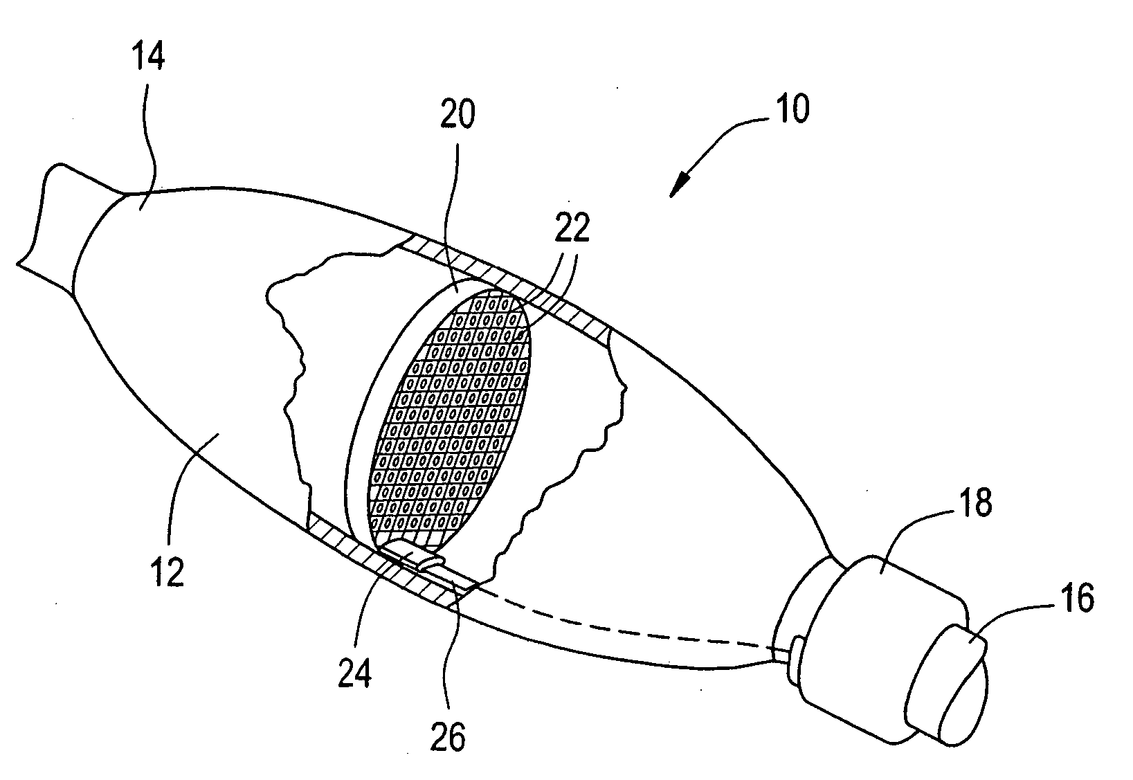
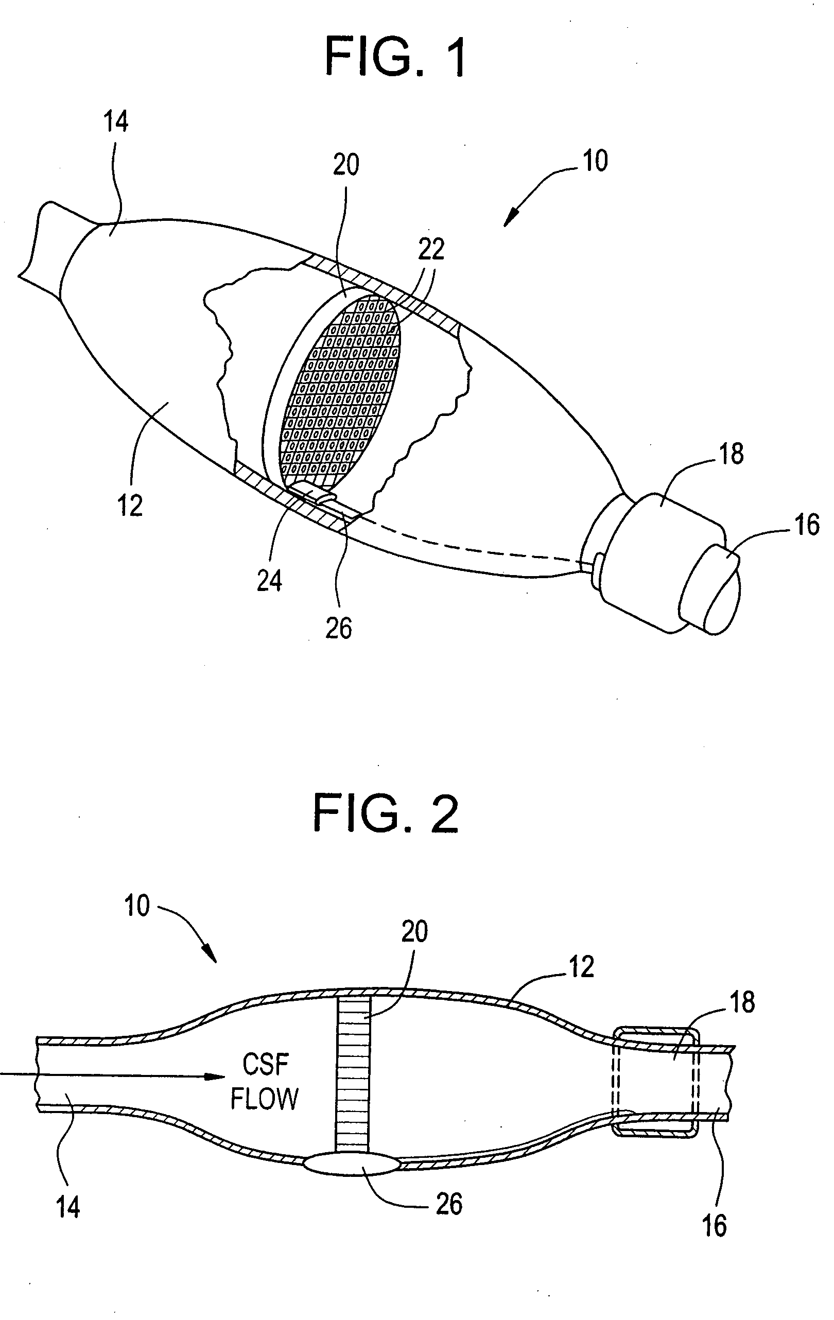
[0048]FIG. 1 is a schematic view of a shunt valve 10 having a valve body 12, a proximal end 14, a distal end 16, and a power supply and electronic controls 18. The shunt valve comprises a valve assembly 20 with a plurality of deflectable valve elements 22, a connector 24, and associated electrical conduits 26 that serve to couple the valve assembly 20 with the power supply and electrical controls 18. The term “deflectable” and variants thereof as used in this specification is intended to include bending, shifting, swinging, stretching and elastic deformation as well as other forms of physical movement.

[0049]FIG. 2 a schematic sectional view of the shunt valve. The valve body 12 houses the shunt valve assembly 20 which has a plurality of deflectable valve elements 22. The shunt valve assembly 20 is designed to facilitate the passage of cerebrospinal fluid (CSF) from the proximal end 14 to the distal end 16 when the pressure differential between the ventricle and the distal cavity is...


PUM


Abstract

Microfluidic shunt valves are disclosed having a deflectable element capable of being held in a closed position to occlude the passage of fluid between an inlet and outlet and, when not held in the closed position, the deflectable element is adapted to oscillate in response to fluid pressure pulses and thereby facilitate fluid passage through the valve. Controls for activating the deflectable element to permit fluid passage are also included.

Description

BACKGROUND OF THE INVENTION [0001] The present invention relates generally to the treatment of hydrocephalus, and more particularly relates to cerebrospinal fluid (“CSF”) shunts. [0002] Hydrocephalus is a condition in which cerebrospinal fluid accumulates in the ventricles of the brain. This accumulation of fluid increases the pressure within the ventricles and without medical intervention can cause brain damage and / or death to the patient. A common treatment for hydrocephalus is to use a fluid shunt system to drain excess CSF from the cerebral ventricles to a second body cavity, typically the peritoneal cavity. By draining the excess fluid, the elevated intracranial pressure is relieved. CSF shunts are well known and used broadly to treat patients with chronic hydrocephalus. [0003] Generally, fluid shunt systems include a valve mechanism for controlling or regulating the flow rate of fluid through the system. Shunt systems typically permit fluid flow only when the fluid pressure re...

Claims


Application Information

Patent Timeline
Patent Type & Authority Applications(United States)
IPC IPC(8): A61M5/00
CPCA61M27/006F15C5/00A61M2205/0244Y10T137/6086Y10T137/87169Y10T137/2365Y10T137/86549
Inventor MADSEN, JOSEPH R.IVANOV, DENTCHO
Owner CHILDRENS MEDICAL CENT CORP
Why Eureka
Try Eureka