Valve holder

a valve and handle technology, applied in the field of valve holders, can solve the problems of paravalvular leakage, difficult to avoid suture entanglement, leaflets and stents distal to the handle, etc., and achieve the effect of improving visibility and accessibility

Active Publication Date: 2006-10-26
MEDTRONIC INC
View PDF26 Cites 47 Cited by
  • Summary
  • Abstract
  • Description
  • Claims
  • Application Information

AI Technical Summary

Benefits of technology

[0014] Accordingly the present invention is directed to a valve holder that is removably attached to the prosthetic

Problems solved by technology

Entanglement of the valve sutures with the holder, holder sutures or holder suture knots could cause paravalvular leakage when the holder is removed after the valve has been secured.
The handle and the holder in prior art designs block visibility along the axis of the valve making suture entanglement difficult to avoid.
In attaching a mitral valve for example, the leaflets and stent are

Method used


Image

  • Valve holder
  • Valve holder
  • Valve holder

Examples


example 1

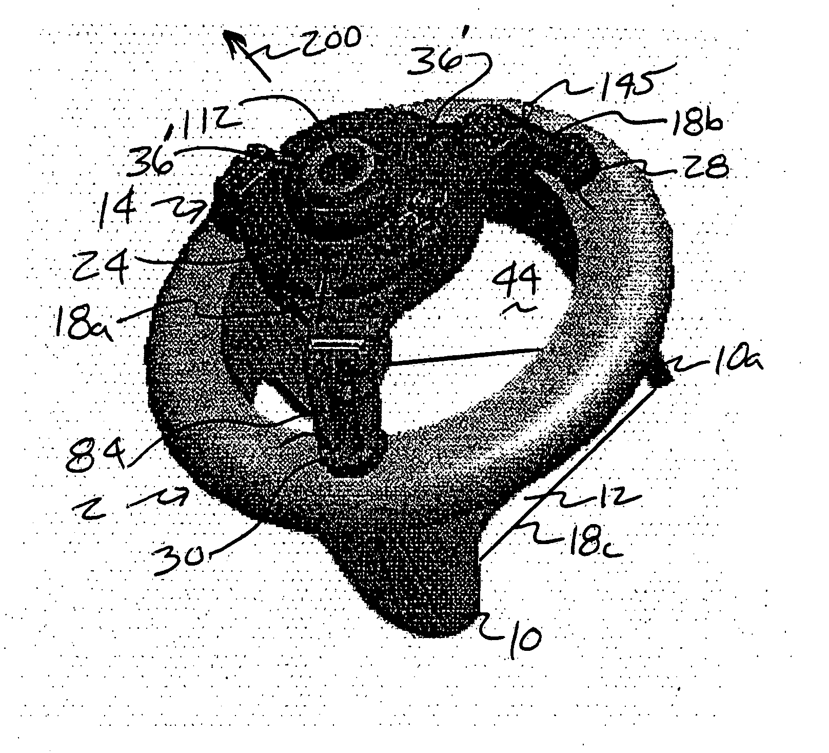
[0088] The release force 200 (FIG. 12) to remove the valve holder 14 from the valve 2 is an improved, lower release force 200 than prior art designs. The lower release force 200 reduces the chance of pulling the valve sutures 52 loose. FIG. 14 illustrates the release force 200 required to pull the holder sutures 18, 20, 22 free of the valve 2 comparing the prior art holder and the present invention. The reduced release force 200 (average 30% lower) results in less pull on the valve sutures 52 insuring the integrity of the attachment of the valve 2 to the patient.

TABLE 2FIG. 14 Summary AnalysisPresentPrior ArtInventionRelease ForceRelease Force(lbf)(lbf)Mean0.920.68Std. Deviation0.370.12

[0089] The present invention also provides for increased visibility or access over prior art holders. This is believed to increase visibility during use of the holder as well as access to the site for substances such as fluids. This may be accomplished by reducing the structure of the holder that bl...


PUM


Abstract

The present invention is an improved apparatus for holding and maneuvering a valve during preparation and attachment to patient. The present invention is particularly useful for increased visibility of the prosthetic valve and the sewing ring to prevent suture entanglement. The present invention is used most effectively with mitral valves having commissure posts on the outflow side of the valve structure but may be used with other valve configurations. The present invention spaces the handle attachment from the valve for improved visibility of the sewing ring and the outlet end of the valve during attachment. The present invention is adapted to safely bend the commissure posts inward at the tips while preventing crashing the commissure posts into each other causing damage. The new holder prevents suture remnants left in a patient by a designed break point for the holder suture. The present invention reduces the release force needed to remove the holder and unthread the holder sutures by an improved design and method of attachment to the prosthetic valve. The improved holder provides a kink free holder suture path to reduce suture entanglement and prevent damage to the implanted valve during holder removal by reducing the release force needed to remove the holder sutures by up to 30%.

Description

CROSS-REFERENCE TO RELATED APPLICATIONS [0001] This application claims the benefit under §119(e)(1), and incorporates herein by reference an entirety of, U.S. Provisional Application No. 60 / 6654,116, filed Feb. 18, 2005 and entitled “Valve Holder.”FIELD OF THE INVENTION [0002] The present invention relates to methods used to place prosthetic valves in patients and apparatus used in the methods. More specifically, the present invention relates to tools, apparatus and methods used to hold a heart valve during insertion and attachment during a heart valve replacement procedure. BACKGROUND [0003] Heart valve replacement is a common procedure for patients suffering from heart valve damage due to a variety of ailments and disease. Prosthetic heart valves comprise two main types, mechanical and natural tissue valves. Mechanical replacement heart valves comprise a mechanical apparatus usually made from metal or plastic having mechanisms to allow flow in one direction and resisting flow in t...

Claims


Application Information

Patent Timeline
IPC IPC(8): A61F2/24
CPCA61F2/2409A61F2250/0097A61F2/2427A61F2/2412
Inventor BERGIN, CATHY A.RYAN, TIMOTHY R.
Owner MEDTRONIC INC
Why Eureka
Try Eureka