Load balancing server and system

a load balancing server and load balancing technology, applied in the field of load balancing servers and systems, can solve the problems of inability to handle requests from servers or the like, and achieve the effect of preventing the consumption of resources of multiple servers assigned for serving a single terminal and effective server resources

Inactive Publication Date: 2006-10-26
HITACHI LTD
View PDF10 Cites 149 Cited by
  • Summary
  • Abstract
  • Description
  • Claims
  • Application Information

AI Technical Summary

Benefits of technology

[0006] When a prior-art load balancing server determines which server should be assigned, referring to information included in the payload of an IP packet (e.g., layer 7 information and application layer information in a SIP message), it is needed to terminate encrypted communication once at the load balancing server and decrypt the communication. A first challenge and object of the present invention is to prevent an increase in the processing load of the load balancing server due to this decryption task, which results in a reduced effect of load balancing and forwarding delay.
[0007] For prior-art load balancing servers using redirect notification, no consideration is taken for things after a step of notifying a terminal of the assigned server. In some case, the terminal might permanently continue to connect to the assigned server thus notified. A second challenge and object of the present invention is to prevent long concentration of processing load on a particular server assigned, which results in a reduced effect of load balancing.

Problems solved by technology

It is impossible to handle a request from a server or the like without the function of redirection by redirect notification (e.g., an ordinary SIP proxy server).

Method used


Image

  • Load balancing server and system
  • Load balancing server and system
  • Load balancing server and system

Examples


first embodiment

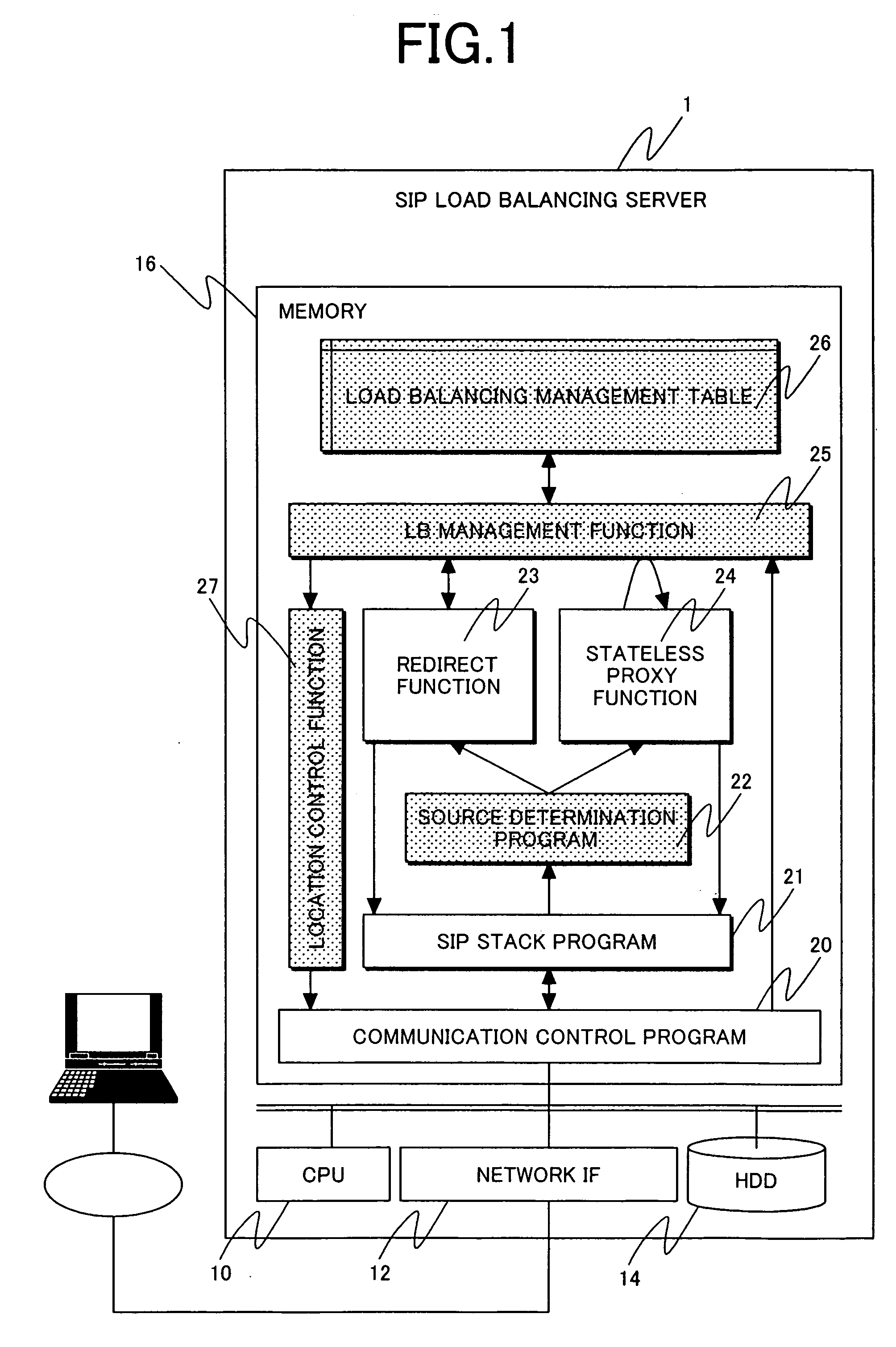
[0037]FIG. 1 shows an example of a SIP load balancing server architecture for a first embodiment of the invention. Although SIP is taken as an example in the first embodiment, the invention may be applied to other application layer protocols (other session control protocols). The SIP load balancing server 1 includes a CPU (10), a memory (16), and a storage device (14) and a suite of programs for control which will be detailed below is stored. When the SIP load balancing server operates, the control program suite is loaded into a memory space provided in the mainframe and executed by the CPU. The storage device may be installed in the mainframe, may be installed as an external storage device in another frame, or may be connected to the server via a network.

[0038] The load balancing server shown in FIG. 1 may include a user interface for allowing a user authorized to manage the server to operate the load balancing server. The user interface preferably includes, for example, a keyboar...

second embodiment

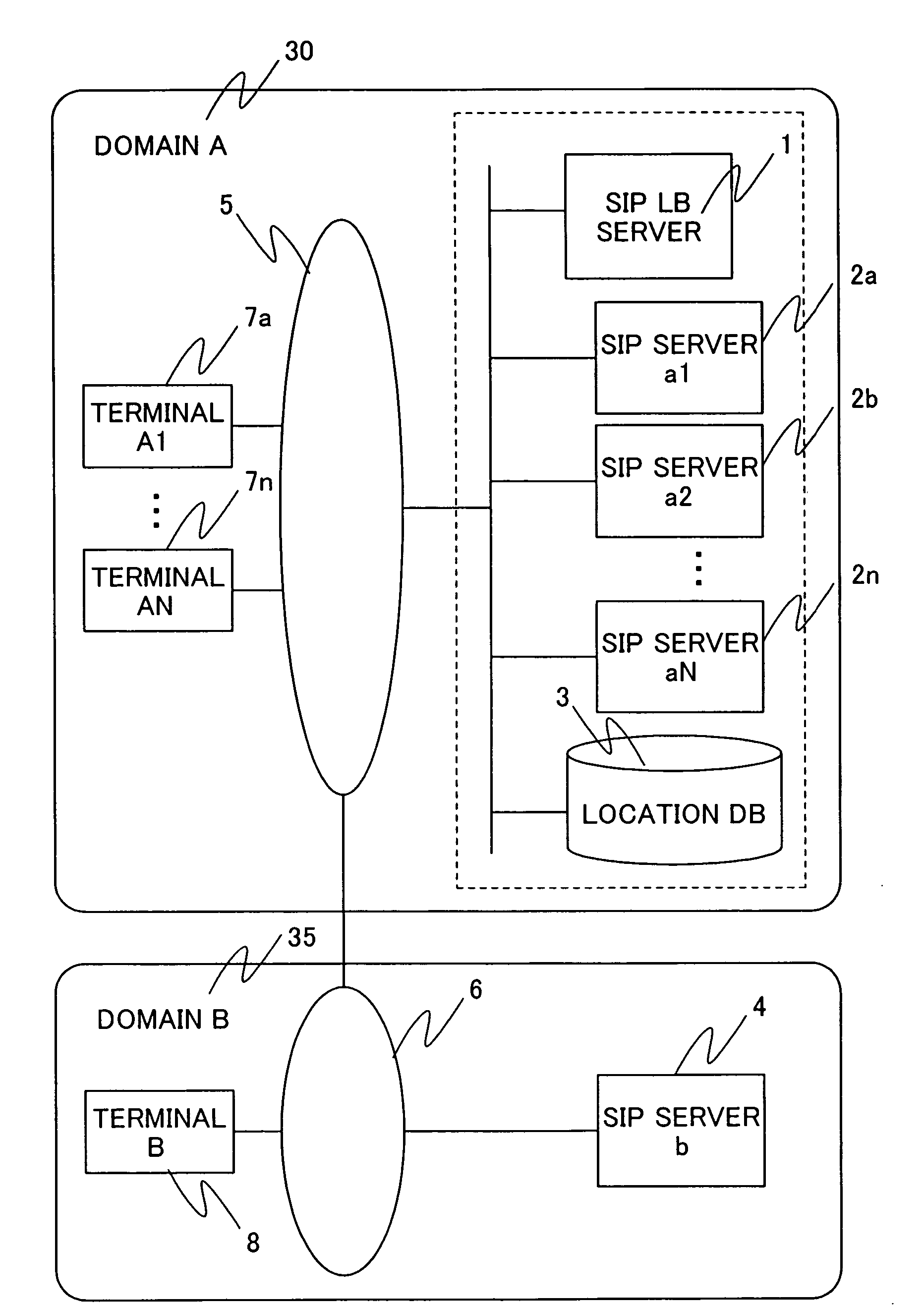
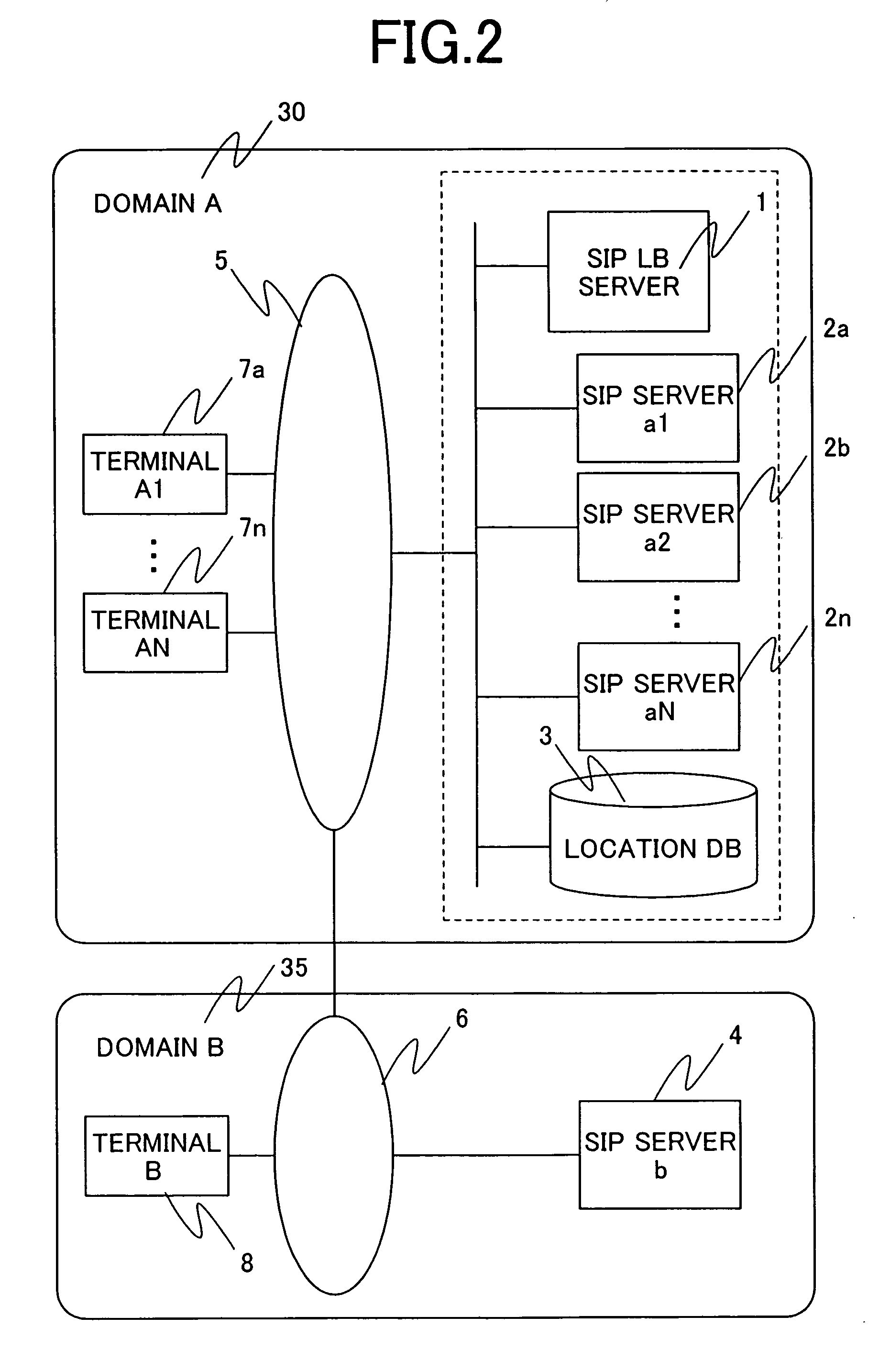
[0070] In a SIP load balancing system for a second embodiment, FIG. 11 shows an example of a method for handling a request message addressed to a terminal 7 in the local domain, routed via a SIP server 4 in another domain.

[0071] A request message which is transmitted from a terminal 8 belonging to another domain (domain B) 35, addressed to the terminal 7 belonging to the local domain (domain A) is first transmitted to the SIP server b 4 to which the terminal 8 belongs (F100). The SIP server b4 forwards the received request message to a SIP server in the domain to which the destination terminal 7 belongs. In the operation of the SIP load balancing system for the second embodiment, the SIP LB server 1 is assigned a SIP server representative address (e.g., domain A.co.jp) for managing the domain A. Thus, the request message which is forwarded via the SIP server b4 is sent to the SIP LB server 1 (F101).

[0072] On the SIP LB server 1 that received the request message sent from the SIP s...

third embodiment

[0083]FIG. 13 shows an example of a method of communication between terminals in one domain in a SIP load balancing system for a third embodiment. A terminal a1 (7a) and a terminal aN (7n) have set up continuous connections (sessions), respectively, with a SIP server a1 (2a) and a SIP server aN (2n) notified from the SIP LB server 1 in the same procedure as described for FIG. 3. In this state, how a request message from the terminal a1 is routed to the terminal aN is described.

[0084] The request message issued by the terminal a1 is first sent to the SIP server a1 having an established session with the terminal a1 (F130). By referring to the destination of the message, the SIP server a1 knows that the destination is a terminal belonging to the same domain. Now, if the server maintains location information for the terminals that it serves in a cache on a memory or a local hard disk, it checks whether the destination terminal's information is found in the location information in the c...


PUM


Abstract

When load balancing (LB) for SIP message communication is performed across multiple SIP servers, the number of messages that must be processed by an LB server is reduced. The SIP LB server includes an LB management means which, if the previous hop source of a received request message is a terminal in the local domain, determines which SIP server to serve the terminal, and a redirect function which notifies the message source terminal in the local domain of the address of the serving SIP server. The SIP LB server further includes an LB management table which, if the previous hop source of a received request message is other than a terminal in the local domain, is searched to find a SIP server serving communication with a destination terminal in the local domain, and a stateless forwarding function which statelessly forwards the received request message to the resolved SIP server address.

Description

CLAIM OF PRIORITY [0001] The present application claims priority from Japanese application JP 2005-125850 filed on Apr. 25, 2005, the content of which is hereby incorporated by reference into this application. FIELD OF THE INVENTION [0002] The present invention relates to a technique in which a server that performs session control and management determines a destination to which a received message should be forwarded and, in particular, to a technique for processing communication traffic by distributing loads across multiple session control servers. BACKGROUND OF THE INVENTION [0003] Load balancing servers have heretofore been evolved for the purpose of handling huge traffic by sharing traffic which would otherwise have to be handled by a Web server across multiple Web servers having equivalent functions. Load balancing is now being developed, extending its scope to cover a variety of devices and protocols involving routers, mail servers, VPN gateways, etc., besides Web servers. [00...

Claims


Application Information

Patent Timeline
Patent Type & Authority Applications(United States)
IPC IPC(8): G06F15/173G06F9/50H04L45/24
CPCH04L29/06027H04L67/1008H04L65/1006H04L67/1002H04L67/1029H04L65/1104H04L67/1001H04L65/1101
Inventor YUMOTO, KAZUMAKAWAI, ERIYOSHIZAWA, MASAHIRO
Owner HITACHI LTD
Why Eureka
Try Eureka