
Computer volatile memory power backup system

a volatile memory and backup system technology, applied in computing, error detection/correction, instruments, etc., can solve the problems of loss of video memory, loss of video memory information, loss of processor state and all information in volatile memory of the computer, etc., to reduce power requirements, reduce power demand, and reduce power requirements

Inactive Publication Date: 2006-10-26
MICROSEMI
View PDF48 Cites 62 Cited by
  • Summary
  • Abstract
  • Description
  • Claims
  • Application Information

AI Technical Summary

Benefits of technology

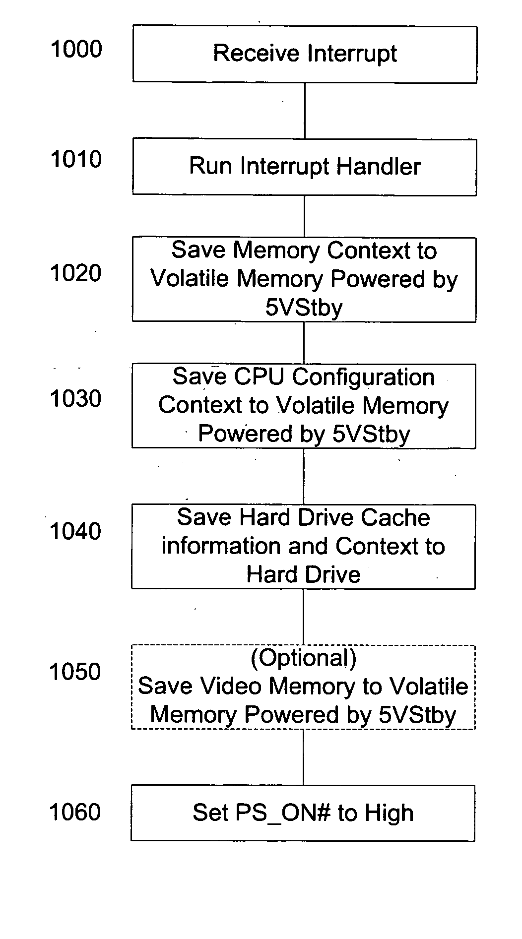
[0018] In one embodiment, standby power is fed to the input of the computer power supply. The interrupt routine of the processor sends a logic high PS_ON# signal to the power supply, and the power supply responsive to logic high signal shuts down all power outputs with the exception of the standby power supply. In an exemplary embodiment the interrupt routine reduces the power demand to the amount available from the backup power before the loss of output derived from the AC mains supplied power supply. In another embodiment any short term power mismatch is supported by energy storage in a capacitor, the capacitor preferably being arranged to store energy of a high voltage. Power is thus supplied for the volatile memory via the standby power supply of the computer, the power for the standby power supply being delivered from the backup power source, which is preferably a PoE connection.
[0019] In one embodiment the reduction in power demand is a result of the interrupt routine powering down devices receiving power from the power supply. In an exemplary embodiment the control hub or southbridge is powered down thereby reducing power requirements to a level supportable by the backup power source.
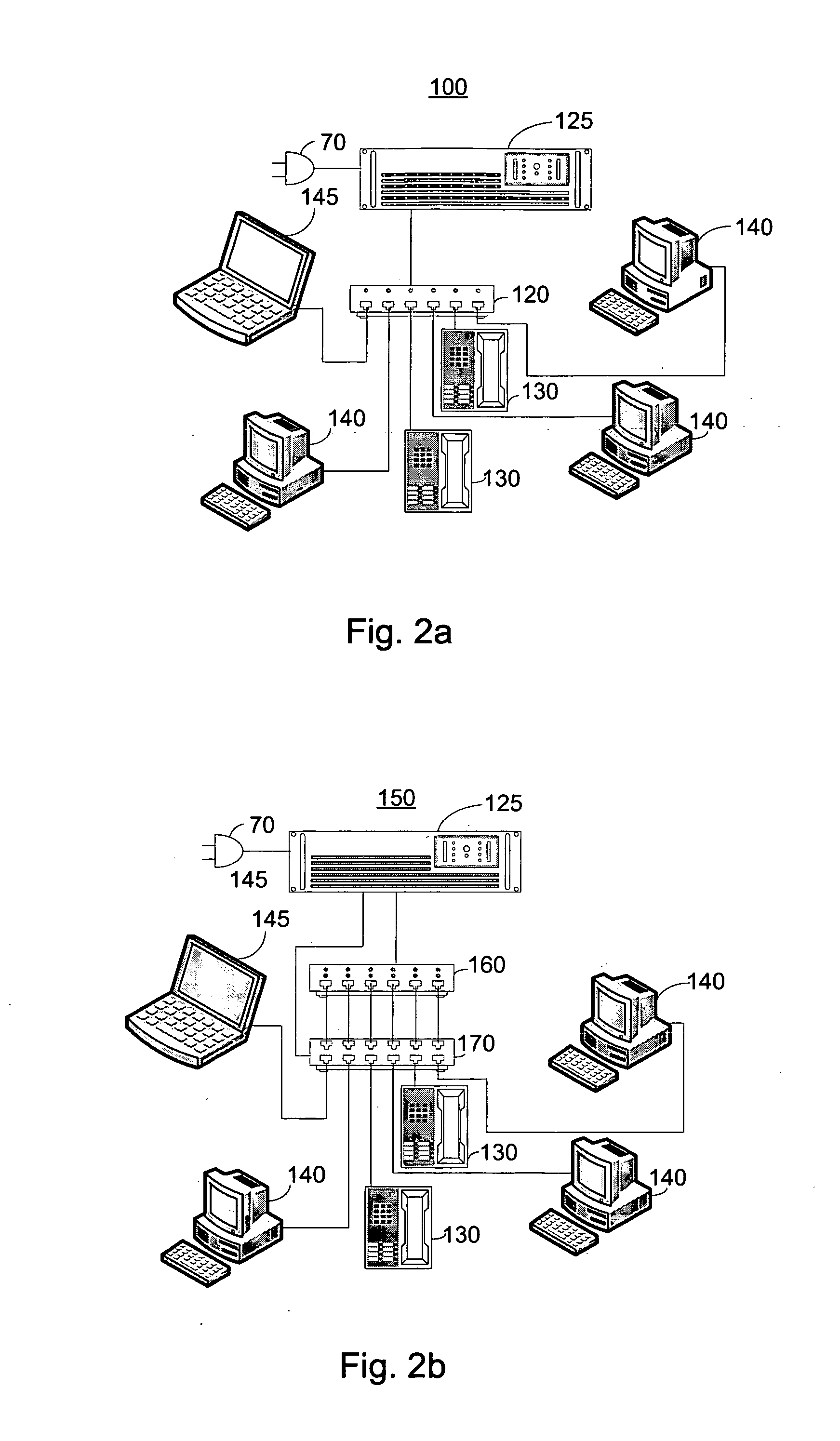
[0020] In another embodiment backup power, preferably received via PoE, operates a plurality of DC / DC converters the output of which are ORed with each of respective plurality of voltage outputs of the computer power supply. Power is thus maintained for all devices of the computer for a sufficient amount of time to enable the interrupt routine to complete its storage operation. In one further embodiment the interrupt routine powers down devices thus reducing the total power demand to less than or equal to the amount of available backup power. In an exemplary embodiment the control hub or southbridge is powered down thereby reducing power requirements to a level supportable by the backup power. Power is thus supplied for the volatile memory via a separate power supply from the main computer power supply, the separate power supply receiving its power from the backup power source.

Problems solved by technology

Power over Ethernet (PoE) supplies a limited amount of power to an attached powered device, with the aforementioned standard limiting the average input power of a powered device to a maximum of 12.95 watts.
At the expiration of the hold up time, computer power is no longer reliably supplied and both the processor state and all information in volatile memory of the computer is lost.
Similarly any information stored in video memory, such as fonts being displayed on the screen, is lost.
The provision of a UPS for each computer is costly and requires additional space at each computer location.
Furthermore, maintenance of a separate UPS at each computer adds to overhead.
Such a dedicated wiring is costly to install and expensive to modify when changing the location of computers.
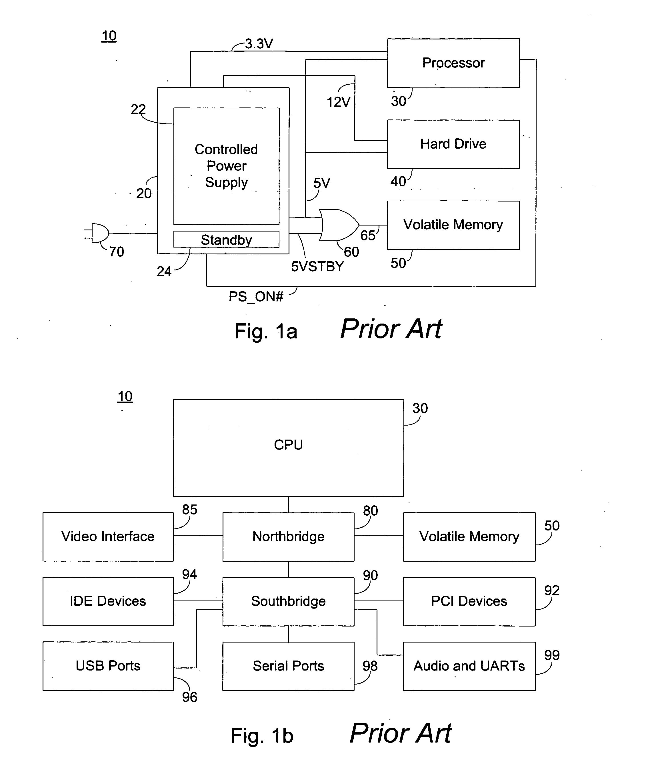
Unfortunately, in the event of a loss of AC mains power, CPU 30 lacks sufficient time and warning to proceed to the standby mode in an orderly fashion, as the hold up time of 17-20 milliseconds is insufficient.
Furthermore, no mechanism is supplied to initiate the standby mode in the event of a loss of AC mains power.
Additionally, in the event of a loss of AC mains power, there is no source of electrical power to maintain power bus 65.
Unfortunately, the ACPI is unable to reduce power consumption in the event of a mains power failure, as operating power for computer 10 is not supplied.
Furthermore, in the event of a mains power failure, power is not supplied for volatile memory 50, and thus in the absence of supplied power all information stored thereon is lost.
Other architectures, specifically including an Intel Hub Architecture exhibit similar issues regarding powering and loss of information and processor state upon AC mains failure.

Method used


Image

  • Computer volatile memory power backup system
  • Computer volatile memory power backup system
  • Computer volatile memory power backup system

Examples


Embodiment Construction

[0051] The present embodiments enable a backup of a computer in the event of power failure by powering a volatile memory, preferably by utilizing power over Ethernet. In particular, a failure of mains power is detected and an interrupt to the processor is generated, with the interrupt routine saving context information and data to volatile memory locations receiving backup power during mains failure. In an exemplary embodiment the interrupt routine initiates a sleeping state managed by an operating system.

[0052] Before explaining at least one embodiment of the invention in detail, it is to be understood that the invention is not limited in its application to the details of construction and the arrangement of the components set forth in the following description or illustrated in the drawings. The invention is applicable to other embodiments or of being practiced or carried out in various ways. Also, it is to be understood that the phraseology and terminology employed herein is for ...


PUM


Abstract

A system for backing up a computer in the event of a mains power failure, the system comprising: sensing means operative to sense a failure of mains power; means for receiving power over data communication cabling; a volatile memory; means for feeding power from the means for receiving power to the volatile memory; and an interrupt generating means for generating an interrupt to a processor responsive to the sensing means, the processor being operative responsive to the generated interrupt to store status information on the volatile memory.

Description

CROSS-REFERENCE TO RELATED APPLICATIONS [0001] This application claims priority from U.S. Provisional Patent Application Ser. No. 60 / 666,575 filed Mar. 31, 2005 entitled “Computer Power Back-Up Utilizing Power Over Ethernet”, and U.S. Provisional Patent Application Ser. No. 60 / 690,137 filed Jun. 14, 2005 entitled “Computer Volatile Memory Power Backup System” the entire contents of each of which are incorporated herein by reference.BACKGROUND OF THE INVENTION [0002] The present invention relates to the field of backup powering, and more particularly to a means for backing up a computer during mains power failure by powering a volatile memory, preferably by utilizing power over Ethernet. [0003] The growth of local and wide area networks based on Ethernet technology has been an important driver for cabling offices and homes with structured cabling systems having multiple twisted wire pairs. The ubiquitous local area network, and the equipment which operates thereon, has led to a situa...

Claims


Application Information

Patent Timeline
IPC IPC(8): G06F11/00
CPCG06F11/1441
Inventor FELDMAN, DANIELPEKER, ARKADIYKORCHARZ, DRORKAHN, SIMONSALEM, MOHAMAD A.
Owner MICROSEMI
Learn More