Relating to fuel injection systems

a fuel injection system and fuel injection technology, applied in the direction of fuel injection pumps, liquid fuel feeders, machines/engines, etc., can solve the problems of system not being able to facilitate variations on an optimum scale and certain injection profiles

Inactive Publication Date: 2006-11-02
DELPHI INT OPERATIONS LUXEMBOURG S A R L
View PDF9 Cites 37 Cited by
  • Summary
  • Abstract
  • Description
  • Claims
  • Application Information

AI Technical Summary

Benefits of technology

[0026] Preferably, the fuel pressurising arrangement includes a pumping chamber and pressurising means for increasing the pressure of fuel in the pumping chamber.

Problems solved by technology

In addition, any injection profile is subject to certain practical constraints, namely a minimum volume of fuel must be delivered within a particular time frame that coincides with the cam cycle.
Whilst the fuel injection system 400 has great advantages for allowing boot shaped injections to be realised, in some circumstances the system does not facilitate variations on an optimum scale.

Method used


Image

  • Relating to fuel injection systems
  • Relating to fuel injection systems
  • Relating to fuel injection systems

Examples


Embodiment Construction

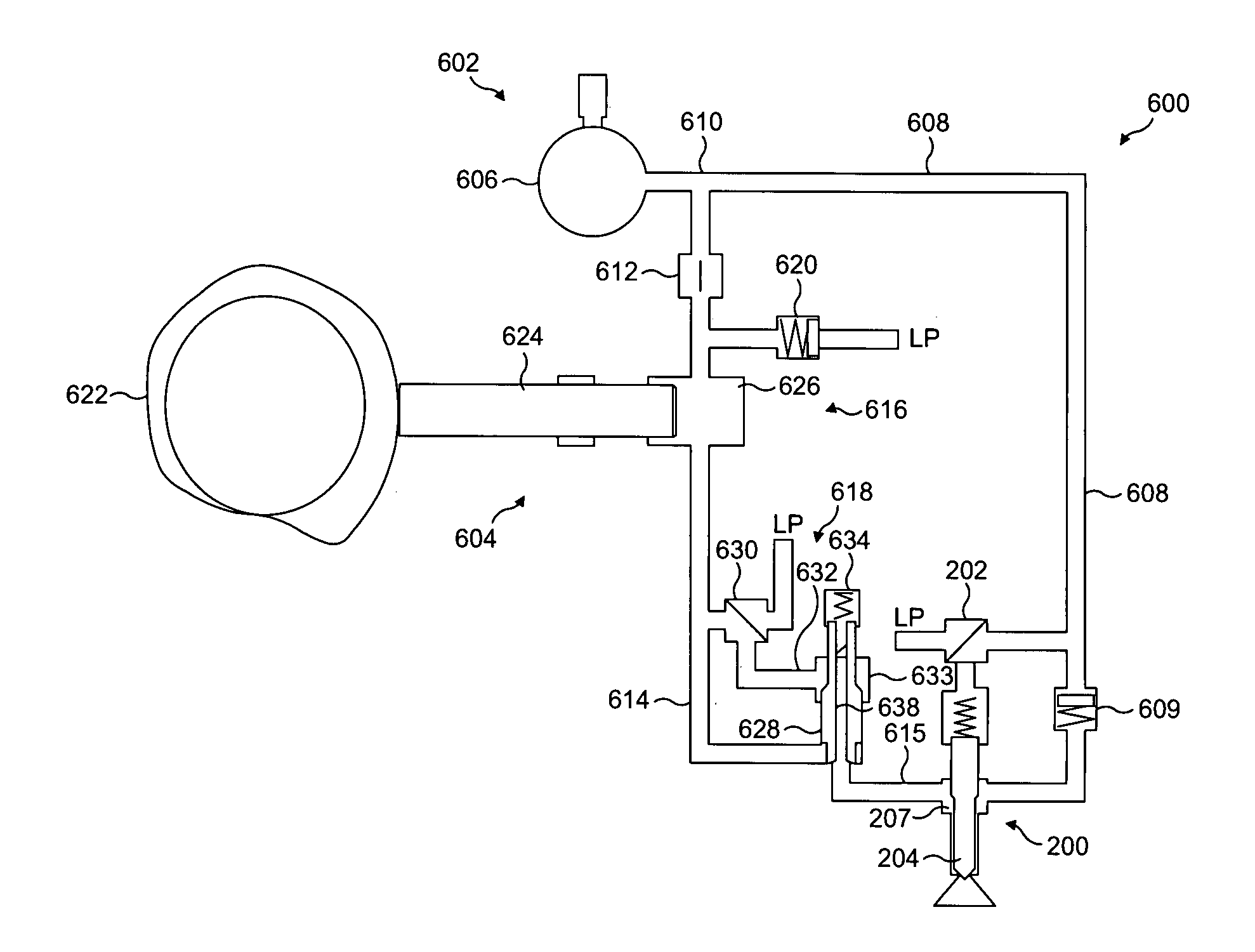
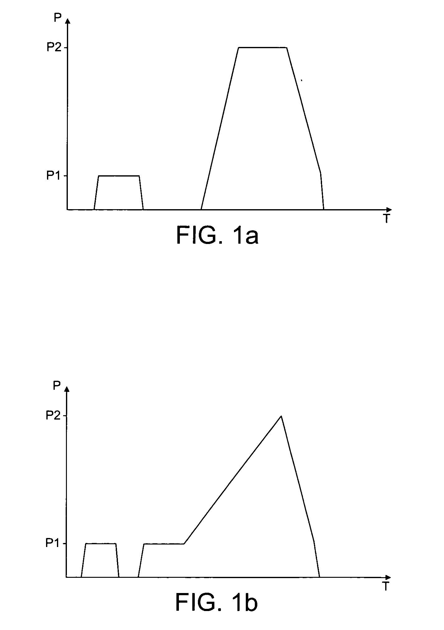
[0042] With reference to FIG. 6, a booster fuel injection system 600 for implementing a presently preferred embodiment of the present invention is now described. The booster fuel injection system 600 facilitates fuel injections which follow a boot injection profile by enabling an injection to commence at rail pressure whilst simultaneously boosting the pressure for the second part of the boot profile, such that a high peak pressure is achieved.

[0043] The booster fuel injection system 600 is comprised of a rail pressure fuel supply 602, a fuel pressurising arrangement (also referred to as a pressure boosting arrangement) 604 and the fuel injector 200 described previously. The rail pressure fuel supply 602 is comprised of an accumulator volume 606 and a rail pressure line 608 which communicates directly, via a first non-return valve 609, with the injector 200. The rail pressure fuel supply 602 of the booster fuel injection system 600 supplies the pressure boosting arrangement 604 wit...


PUM


Abstract

A fuel injection system for supplying pressurised fuel to a fuel injector (200) comprises an accumulator volume (606) for supplying fuel at rail pressure (P1) to the fuel injector (200) through a rail fuel supply passage (608) and a fuel pressurising arrangement (604) for supplying fuel at a selected pressure greater than rail pressure (P2) to the fuel injector (200) through a pressurised fuel supply passage (614). A fuel shut-off valve (618) is provided in the system which is operable between a closed position in which fuel is retained within the pressurising arrangement (604) and an open position in which pressurised fuel is supplied to the injector (200) from the pressurising arrangement (604) during an injection of fuel from the rail fuel supply passage (608). Operating the shut-off valve in this way provides a boost in the fuel pressure delivered during an injection event.

Description

FIELD OF THE INVENTION [0001] The present invention concerns improvements relating to fuel injection systems for internal combustion engines and provides, more specifically, a fuel injection system which is capable of providing a range of injection pressure, or injection rate, characteristics for a given injector. The invention also relates to a control method for such a fuel injection system. BACKGROUND TO THE INVENTION [0002] Within current fuel injection systems a pump is used to deliver fuel to the engine cylinders via a high pressure supply line and, in the course of an ‘injection’, fuel enters a cylinder through one or more apertures which otherwise remain closed by seated injection needles. Typically, a vehicle travelling at around 30 miles per hour, say, will require tens of injections to be made into each of its engine cylinders per second. [0003] Research has shown that, for a given injector, significant improvements in combustion quality and efficiency are achieved by rap...

Claims


Application Information

Patent Timeline
Patent Type & Authority Applications(United States)
IPC IPC(8): F02M63/00F02M69/00F02M59/46
CPCF02M45/04F02M47/027F02M2200/40F02M59/366F02M63/0225F02M59/102
Inventor KNIGHT, ANDREW
Owner DELPHI INT OPERATIONS LUXEMBOURG S A R L
Why Eureka
Try Eureka