
Hybrid-type forklift

Active Publication Date: 2006-11-02
TOYOTA IND CORP
View PDF8 Cites 17 Cited by
  • Summary
  • Abstract
  • Description
  • Claims
  • Application Information

AI Technical Summary

Benefits of technology

[0010] The present invention has been made to solve the above-mentioned problems, and it is therefore an object of the present invention to provide a hybrid-type forklift exhibiting a high energy efficiency while allowing a large power to be taken out.

Problems solved by technology

As a result, it is difficult to realize an optimum operating condition for driving the engine at a low fuel consumption rate, with respect to torque patterns of both the cargo handling load and the running load.
Also, since the hydraulic clutches and brakes are controlled to adjust the running speed of the forklift at this moment, a great energy loss is caused in some cases.

Method used


Image

  • Hybrid-type forklift
  • Hybrid-type forklift
  • Hybrid-type forklift

Examples


first embodiment

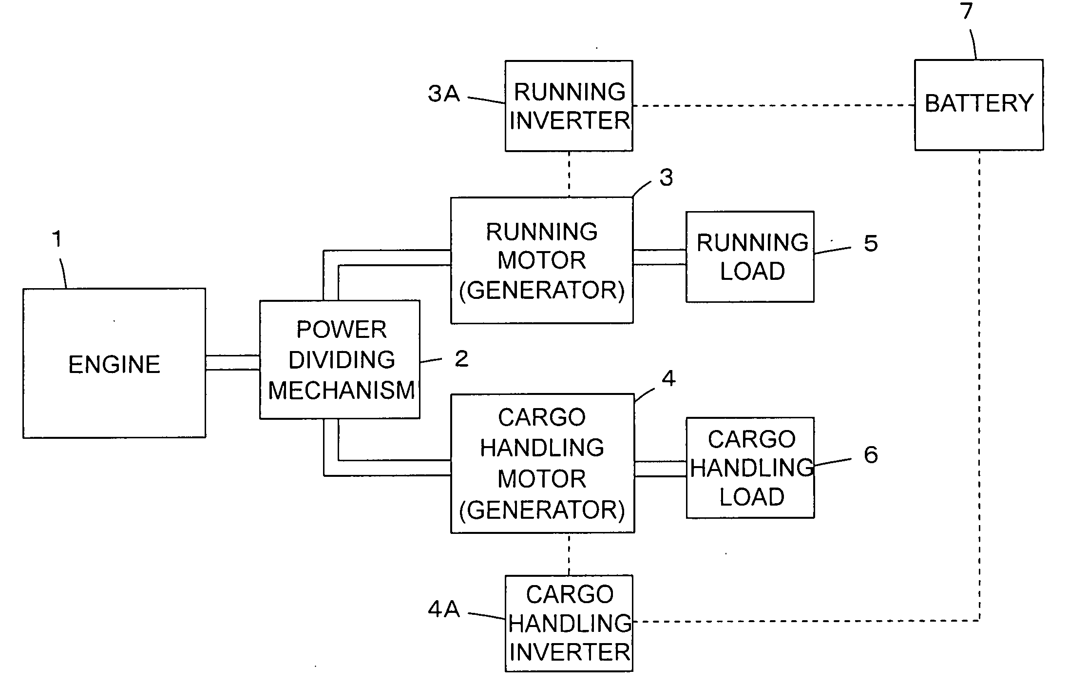
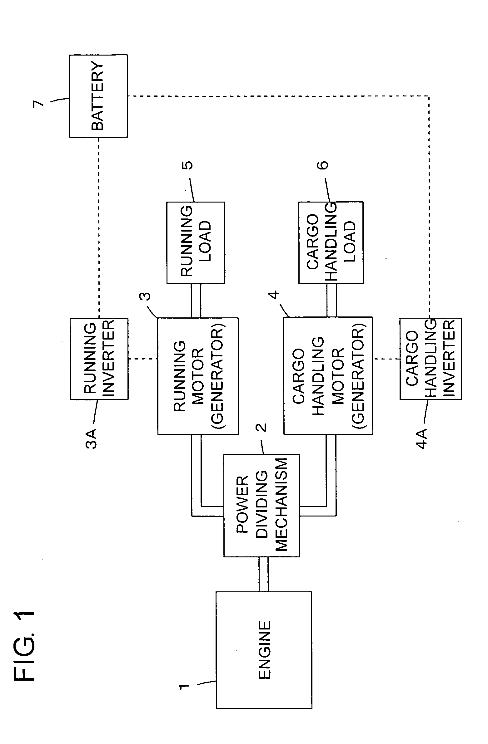
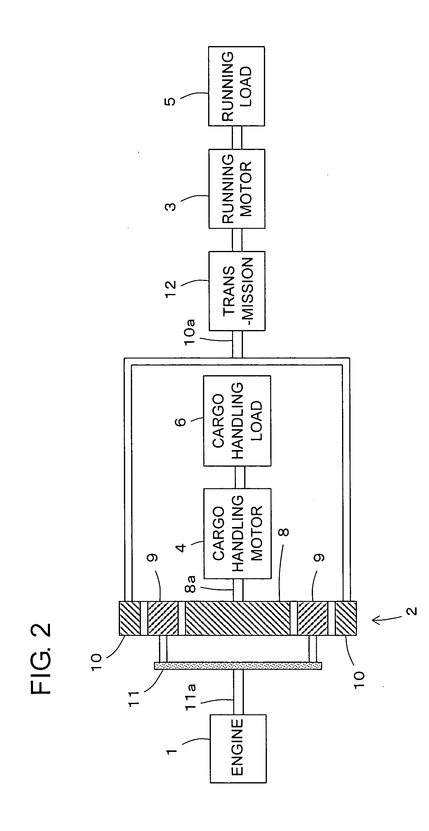
[0031]FIG. 1 shows a configuration of a hybrid-type forklift according to the first embodiment of the present invention. In this forklift, a running motor 3 and a cargo handling motor 4 are connected to an engine 1 via a power dividing mechanism 2. A running load 5 for running is connected to the running motor 3, and a cargo handling load 6 for performing a cargo handling operation such as raising / lowering of a fork is connected to the cargo handling motor 4. The running motor 3 and the cargo handling motor 4 each serves also as an electric power generating means, and are electrically connected to a battery 7 mounted on a base (not shown), via a running inverter 3A and a cargo handling inverter 4A, respectively. Electric power generated by operating the running motor 3 and the cargo handling motor 4 as the electric power generating means is stored into the battery 7 via the running inverter 3A and the cargo handling inverter 4A, respectively. The electric power thus stored is suppli...

second embodiment

[0054]FIG. 7 shows a configuration of a hybrid-type forklift according to the second embodiment of the present invention. This forklift is obtained by providing a clutch 21 between the engine 1 and the power dividing mechanism 2 in the hybrid-type forklift according to the first embodiment of the present invention. That is, as shown in FIG. 8, the engine 1 is connected to the rotational shaft 11a of the carrier 11 of the power dividing mechanism 2 via the clutch 21. The engine 1 can be connected to or disconnected from the power dividing mechanism 2 by means of the clutch 21.

[0055] Power transmission is made possible by connecting the engine 1 and the power dividing mechanism 2 to each other via the clutch 21, thereby making it possible to drive each of the loads 5 and 6 either by the power of the engine 1 alone or by the sum of the power of a corresponding one of the motors 3 and 4 and the power of the engine 1, to charge the battery 7 by the surplus power of the engine 1, as is t...


PUM


Abstract

When an engine is operated, a power dividing mechanism divides power of the engine to output the power to a motor for running operation and a motor for a cargo handling operation, respectively. Each of loads is driven via a rotational shaft of a corresponding one of the motors. By operating the engine and supplying the motors with electric power from a battery to operate the motors, each of the loads can also be driven by the sum of power of the engine and power of a corresponding one of the motors. When surplus power is generated in the power of the engine, each of the motors is operated as an electric power generating unit by the surplus power. As a result, the battery is charged.

Description

BACKGROUND OF THE INVENTION [0001] 1. Field of the Invention [0002] The present invention relates to a hybrid-type forklift, and more particularly, to a hybrid-type forklift having two power sources, that is, an engine and an electric motor. [0003] 2. Description of the Related Art [0004] In general, a forklift known as an industrial vehicle uses an engine or an electric motor as a power source to drive a load for running operation (hereinafter, referred to as running load) and a load for performing a cargo handling operation (hereinafter, referred to as cargo handling load). [0005] For example, JP 6-247190 A discloses an engine-type forklift for driving both the running load and the cargo handling load by means of a single engine. In performing the cargo handling operation while running, the operation of the engine is controlled based on an operation amount of a cargo handling lever, and the running speed of the forklift is controlled by means of a transmission mechanism having hyd...

Claims


Application Information

Patent Timeline
IPC IPC(8): F02B33/00B60K6/365B60K6/40B60K6/445B60K6/547B60K17/04B60L50/16B60W10/30B60W20/00B66F9/24
CPCB60K6/365Y02T10/6239B60K25/00B60K25/06B60L11/123B60L11/14B60L2270/145B60W10/30B60Y2200/15B66F9/20Y02T10/6217Y02T10/646Y02T10/7005Y02T10/7077Y10S903/91Y10S903/917Y02T10/648B60K6/445B60L50/61B60L50/16Y02T10/62Y02T10/7072Y02T10/70Y02T10/64
Inventor ICHIJO, HISASHIIEOKA, SHOICHIKATO, NORIHIKOSUGAI, MASARUUMENO, TAKAJI
Owner TOYOTA IND CORP
Learn More