Air-cooled condenser

a technology of air-cooled condensers and condensers, which is applied in the direction of steam/vapor condensers, stationary conduit assemblies, lighting and heating apparatuses, etc., can solve the problems of large installation height, large substructure, and the inability of air-cooled condensers to achieve uniform distribution, etc., to achieve cost-effective design, large cooling capacity, and small space requirements

Inactive Publication Date: 2006-11-02
SPX COOLING TECH
View PDF12 Cites 13 Cited by
  • Summary
  • Abstract
  • Description
  • Claims
  • Application Information

AI Technical Summary

Benefits of technology

[0005] Therefore the object underlying the invention is to create an air-cooled condenser, using which a large cooling capacity is econ...

Problems solved by technology

However, it has been seen that air-cooled condensers of such a triangular design and large cooling capacity have a large space requirement and also require a large installat...

Method used


Image

  • Air-cooled condenser
  • Air-cooled condenser
  • Air-cooled condenser

Examples


Embodiment Construction

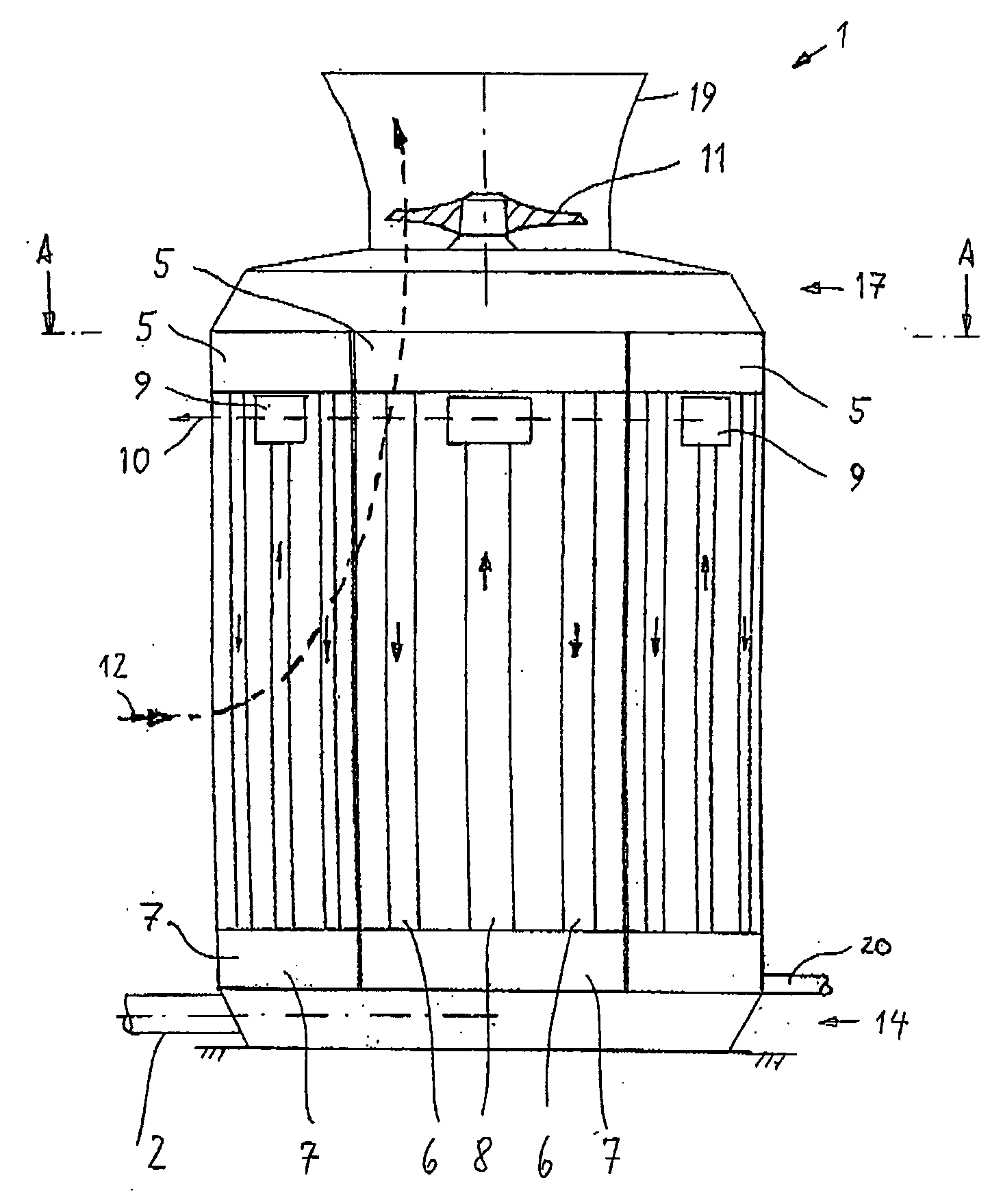
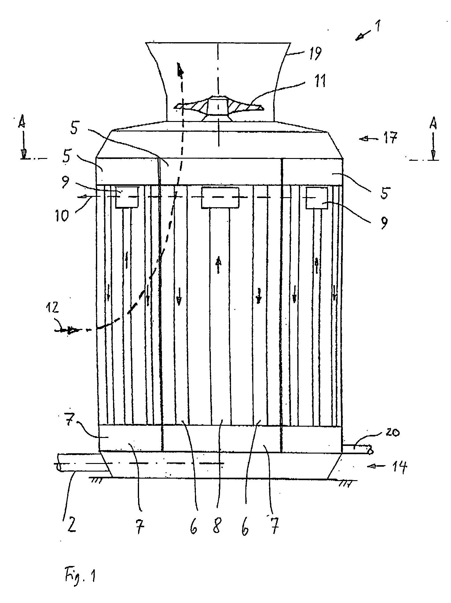
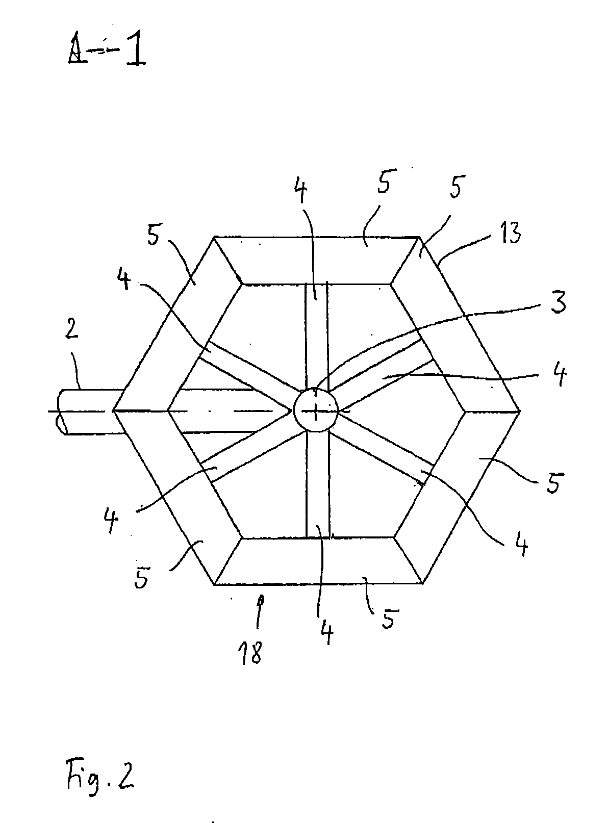
[0022] As is apparent from FIG. 1 and FIG. 2, steam is supplied to the inventive air-cooled condenser 1 using a supply line 2. The steam thereby flows upwards by means of one or more riser ducts 3 and is distributed using distribution lines 4 into a respective distribution chamber 5. It should be pointed out that only one riser duct is illustrated in FIG. 2. The distribution lines are indicated only schematically in FIG. 2; they can be further expanded or divided into several lines toward the distribution chamber 5.

[0023] The distribution chambers 5 are arranged in the upper region of the air-cooled condenser. Below the distribution chambers 5, pipe bundles are arranged, which are indicated schematically using the reference numeral 6. 1, 2 or more pipe bundles can be provided to each sidewall 18 corresponding to the diameter of the fan. The hot steam in the pipe bundles condenses due to the heat exchange with the air flowing past the pipes.

[0024] The liquid condensed in the pipe b...


PUM


Abstract

An air-cooled condenser for the condensation of steam by means of air is described, said air-cooled condenser comprising a steam supply line, at least one upwardly directed pipe bundle, to which the steam to be condensed can be supplied, a condensate drain for the drainage of condensed steam and a fan for the air transport to the pipe bundle. The pipe bundle is arranged below the fan in a sidewall of the air-cooled condenser. Several pipe bundles are thereby arranged in such a way that they form a jacket in the form of a polygon extending in the plumb line, wherein said jacket is closed such that it forms an enclosure on all sides.

Description

CROSS-REFERENCE TO RELATED APPLICATIONS [0001] This application claims priority to German Patent Application No. DE 202005005302.3, filed Apr. 4, 2005, all of the disclosure of which is hereby incorporated by reference in its entirety. FIELD OF THE INVENTION [0002] The present invention relates to an air-cooled condenser for the condensation of steam by means of air. BACKGROUND OF THE INVENTION [0003] It is known that air-cooled condensers comprise pipe elements arranged parallel to one another—the so-called pipe bundles to which the steam to be condensed is supplied. In doing so, every two rows of such pipe bundles are usually arranged in such a way that they are inclined against one another at an acute angle in a gabled form. In the lateral view they form a triangular contour, at the base of which a fan is provided for the supply of air to the pipe bundles. The fan transports air, which is cool in comparison to the steam, to the pipe bundles in such a way that a heat exchange take...

Claims


Application Information

Patent Timeline
IPC IPC(8): F28B9/10F28B1/06
CPCF28B1/06F28B9/02F25B39/04F28D1/04
Inventor VOUCHE, MICHELNAGEL, PHILLIPE
Owner SPX COOLING TECH
Why Eureka
Try Eureka