Aerosol can

a spray dispenser and aerosol can technology, applied in the direction of liquid dispensing, liquid/fluent solid measurement, containers, etc., can solve the problems of not meeting the requirements of convenience, the function of the spray system is only possible within a narrow temperature range, and the effect of large expansion rang

Inactive Publication Date: 2006-11-02
FULMEN DISPENSER
View PDF17 Cites 16 Cited by
  • Summary
  • Abstract
  • Description
  • Claims
  • Application Information

AI Technical Summary

Benefits of technology

[0009] The inventors realized that the stress-strain curve of the elastic material of the filling substance reservoir—with selection of an optimum elastic material-remains at least approximately constant, so that the reservoir's intrinsic elastic force consequently remains unchanged regardless of its expanded condition, and indeed over a relatively large expansion range. This has two advantages: the quality of the spray jet with respect to pressure and volume is largely preserved for the lifetime of the spray dispenser. In addition, towards end of the spray dispenser's life, that is when only a small quantity of filling substance is contained in the reservoir, the material of the reservoir retains sufficient force so that even a residual quantity may be expelled from the reservoir, in large part if not completely.
[0011] A further possibility consists in expanding the reservoir by means other than with the aid of the expansion body itself. Thus, for example, it is conceivable to introduce multiple rods into the reservoir, which extend parallel to the longitudinal axis of the reservoir and are displaced radially, thereby expanding the reservoir. Thereupon the expansion body may be easily introduced with the reservoir in the expanded condition.
[0015] An especially interesting embodiment consists in providing the expansion body with a channel that extends through the expansion body. The channel may pass through the expansion body in the axial direction over its entire length. If the shape of the reservoir is imagined as that of a sack, the channel in the expansion body would open in the area of the bottom of the sack. However, it is also conceivable to provide the channel with lateral outflows, so that several partial channels have their openings on the inner wall of the filling substance reservoir. It is also advantageous to provide channels in the longitudinal direction of the expansion body for purposes of assembling the expansion body, and thus create optimal conditions for the subsequent filling process.
[0019] A barrier layer may also be provided between an inner and an outer layer, preventing the filling substance or components of the filling substance from diffusing through the reservoir.
[0024] There are several possibilities for ensuring expansion of the reservoir. As indicated in the aforegoing, this may be effected by passing the reservoir forcibly over the expansion body. Pincer-type rods are also possible, which are inserted into the reservoir so as to expand it, and then to allow introduction of the expansion body. In addition, it is possible to introduce the expansion body into the reservoir, wherein the expansion body initially is not larger than the reservoir, but subsequently to increase the dimensions of the expansion body by other means, for example by heating or foam expansion or—if a hollow expansion body is used—by inflating it with a liquid or gaseous medium. Another possibility consists in inserting an expansion body into the reservoir that is not larger than the reservoir and then causing it to swell using components added to or contained in the filling substance, thus causing the dimensions thereof to increase and creating the necessary state of stress.

Problems solved by technology

This principle is the worst, because the gas propellant is known to be highly harmful to the environment.
In particular, because the gas propellant has strong dependency on its temperature, the function of the spray system is only possible within a narrowly defined temperature range.
However, this principle does not meet the requirement of convenience.
This principle has one disadvantage.
This is that the elastic force is constantly weakened over the course of time as the filling substance reservoir becomes progressively emptier.
This means that the spray pressure and thus also the volume of the spray jet expelled through the spray nozzle diminishes over time.
The resulting effort thus changes over the lifetime of a spray dispenser, which is undesirable.

Method used


Image

  • Aerosol can
  • Aerosol can
  • Aerosol can

Examples


Embodiment Construction

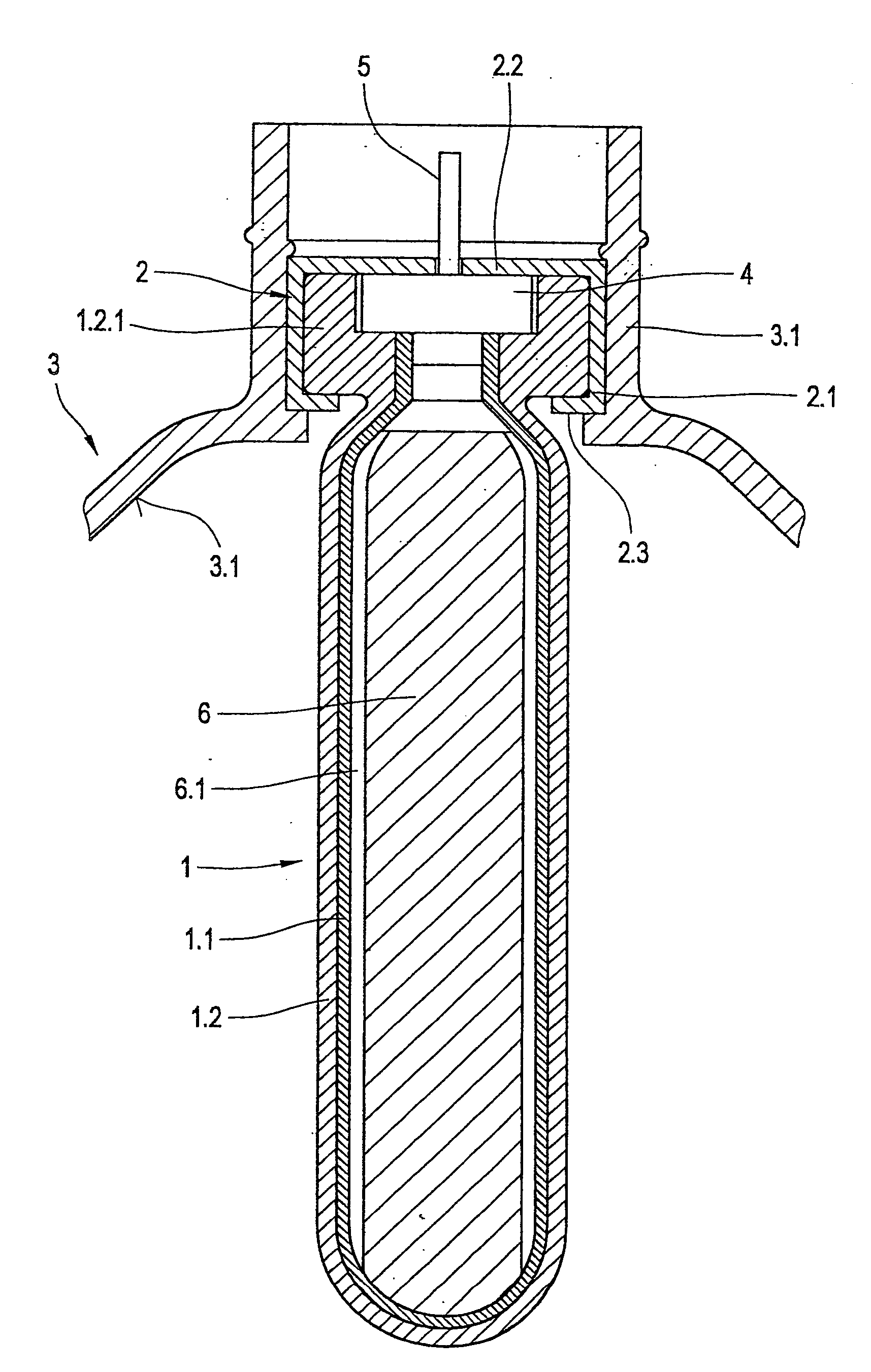
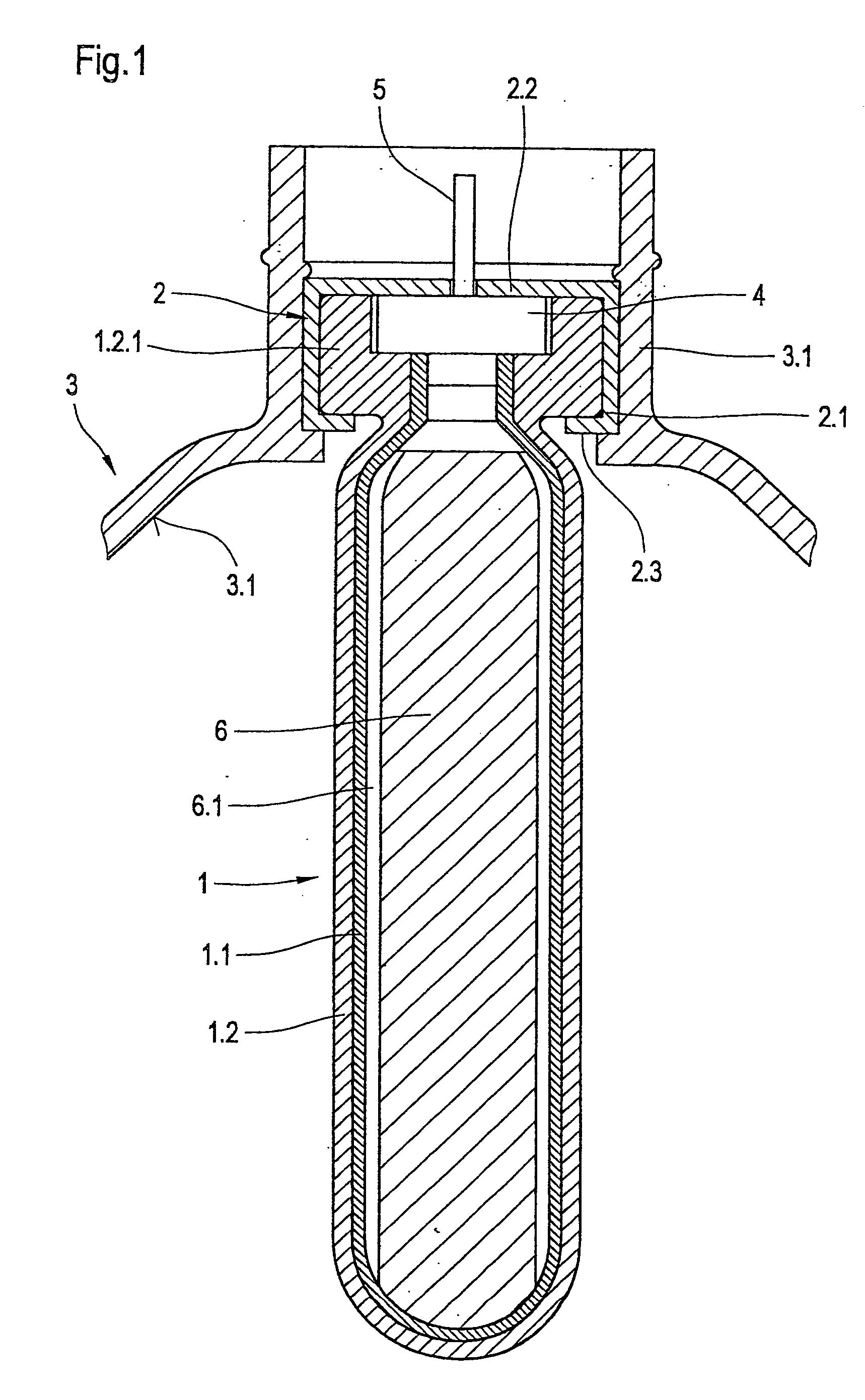
[0029] The spray dispenser shown in FIG. 1 includes a filling substance reservoir 1. In the present case this is double walled. Specifically, it consists of a combination of an external container 1.2 and an internal container 1.1. Internal container 1.1 is made from a material that is inert with respect to the filling substance in question. External container 1.2 is made from an elastic material, which forms the energy storage medium. The two containers are arranged so that their corresponding surfaces are directly adjacent one another. They retain this contact even under any operating state. The internal container thus follows movement of the external container as it expands or contracts.

[0030] External container 1.2 is enlarged in its upper area to form a flange 1.2.1. The flange is cylindrical.

[0031] A pot-shaped mounting body 2 is also shown. This tightly encloses flange 1.2.1. Mounting body 2 has a cylindrical peripheral wall 2.1, a circular plate 2.2 and a collar 2.3.

[0032]...


PUM


Abstract

The invention relates to a spray dispenser having an elastic filling substance reservoir serving as energy storage chamber; an expansion body that is enclosed tightly by the filling substance reservoir in the unfilled condition and at the same time expands the filling substance reservoir against the elastic force thereof; an inlet for the introduction of filling substance during further expansion of the filling substance reservoir into the interstitial area resulting thereby; and an outlet for delivering the filling substance when spraying.

Description

FIELD OF THE INVENTION [0001] The invention relates to a spray dispenser for delivering a substance from a spray nozzle. The substance may be delivered in the form of a fine mist, but also in form of an atomized stream with larger drops. In all cases, such spray dispensers include a filling substance reservoir which receives the filling substance, and also a valve unit that is connected to the filling substance reservoir, with a spray head which in turn is furnished with a spray nozzle. BACKGROUND OF THE INVENTION [0002] There are several possibilities for expelling the filling substance from the filling substance reservoir, and these are realized in various spray dispenser constructions. For example, expulsion of the filling substance by means of a gas propellant is known. This principle is the worst, because the gas propellant is known to be highly harmful to the environment. In particular, because the gas propellant has strong dependency on its temperature, the function of the sp...

Claims


Application Information

Patent Timeline
Patent Type & Authority Applications(United States)
IPC IPC(8): B65D35/28B65D83/14B05B9/04B65D83/00
CPCB65D83/0061
Inventor SCHIEFER, HARTMUT
Owner FULMEN DISPENSER
Why Eureka
Try Eureka