
Viscous fan drive with a fluid control valve

Inactive Publication Date: 2006-11-02
BORGWARNER INC
View PDF10 Cites 12 Cited by
  • Summary
  • Abstract
  • Description
  • Claims
  • Application Information

AI Technical Summary

Benefits of technology

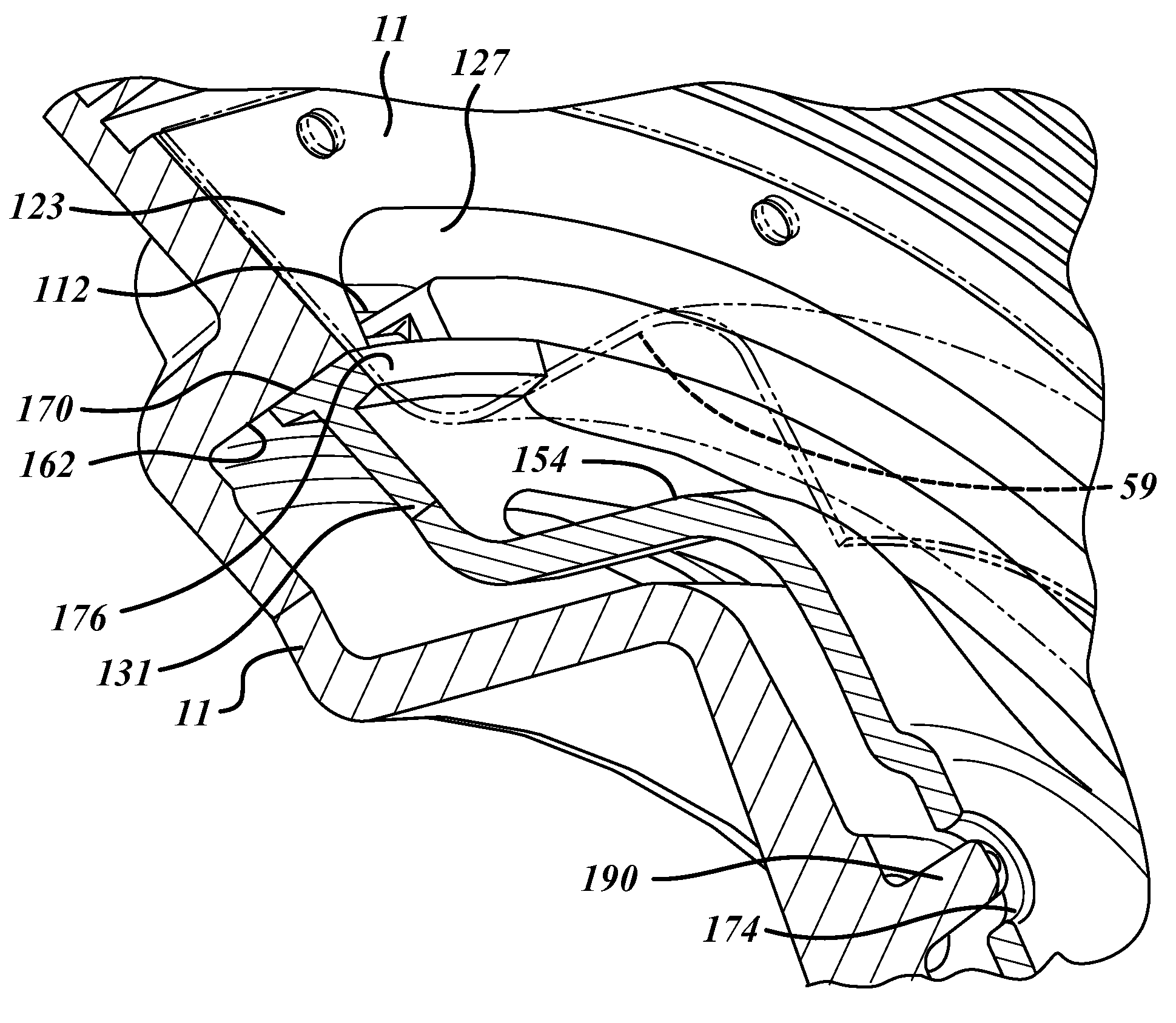
[0012] To ensure proper location of the arc sections relative to the fill holes when the viscous coupling is disengaged, the valve disk is pinned or otherwise coupled to the input coupling assembly in a way that prevents rotational movement of the valve disk. This can be accomplished by utilizing projections contained within a portion of the valve disk that are contained within openings in the input coupling assembly, or alternatively by utilizing projections within the input coupling assembly that are contained within corresponding openings of the valve disk.

Problems solved by technology

Currently available valve disks suffer from many problems associated with their current design.
Most problematic among current designs is that the outer cylinder used to seal and unseal the fill holes requires tight control of the size and roundness on the entire cylinder periphery.
Too much clearance between the valve and the inner surface of the input coupling and the valve leaks.
Too little clearance and the valve sticks.
Moreover, the sealing of the face / end region of the valve to the reservoir cover requires tight control of the flatness and perpendicularity over its entire surface.
Another issue with the present design is particle contamination.
Any little speck of material that gets lodged between the valve and the input coupling will cause sticking of the valve.
Any speck of material between the face / end and the reservoir cover will cause a fluid leakage path.
Yet another issue with the current valve disks is associated with valve positioning as controlled by the magnetic solenoid.

Method used


Image

  • Viscous fan drive with a fluid control valve
  • Viscous fan drive with a fluid control valve
  • Viscous fan drive with a fluid control valve

Examples


Embodiment Construction

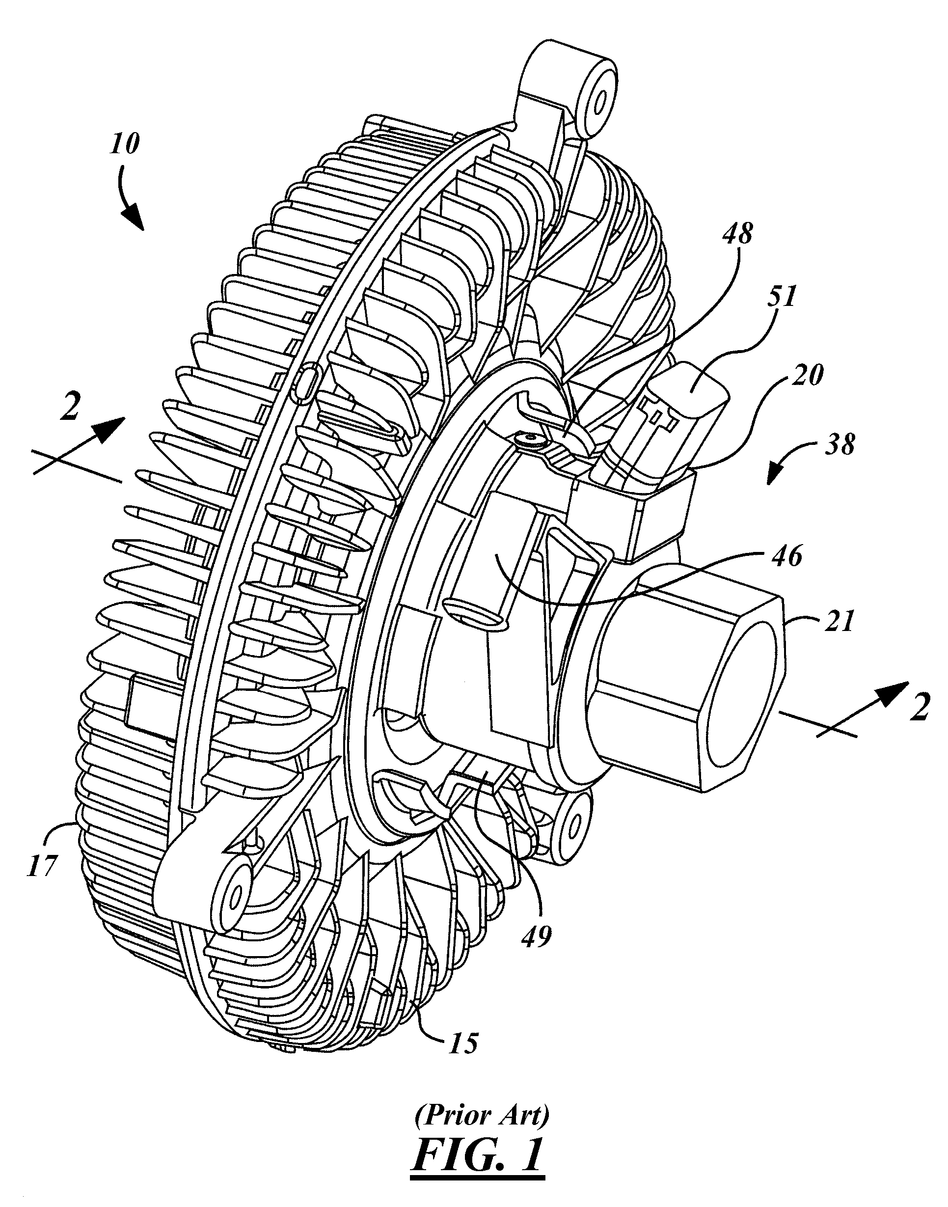
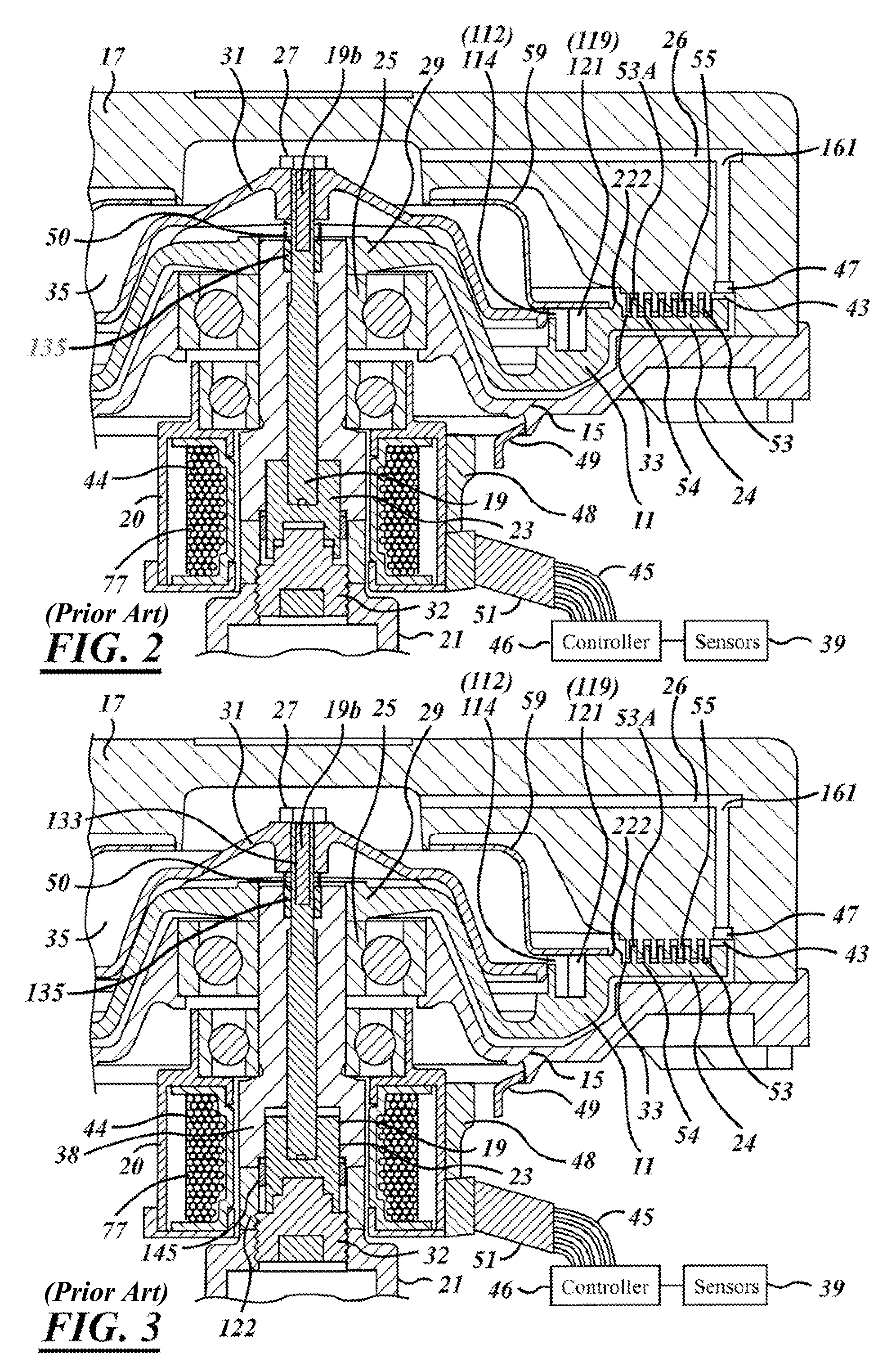
[0026] Referring now to the drawings, which are not intended to limit the invention, FIGS. 1-6 illustrates one form of a fluid-coupling device 10 (“viscous fan drive”) of a type in accordance with the prior art and is described substantially in U.S. patent application Ser. No. 11 / 170,828, filed on Jun. 30, 2005, and entitled “Electronically Controlled Viscous Fan Drive Having Cast Channels”, which is incorporated by reference herein. The fluid-coupling device 10 includes an input-coupling member, or clutch, generally designated 11, and an output-coupling member, or assembly, generally designated 13. The assembly 13 includes a housing member (body) 15, and a cover member (enclosure) 17, the members 15 and 17 being secured together by a rollover of the outer periphery of the cover member 17, as is well known in the art.

[0027] The fluid-coupling device 10 is adapted to be driven by a liquid cooled engine, and in turn, drives a radiator-cooling fan, neither of which is shown herein. Th...


PUM


Abstract

An improved valve disk having a modified cylinder region that includes a first arc section and a second arc section separated by a pair of non-arced sections. These arc sections are positioned to correspond to fill holes in an electronically controlled viscous coupling system. The arc sections have sufficient length and height to seal over the fill holes when the viscous coupling is in a disengaged position. The arc sections each have a face / end portion that each seal to the reservoir cover when the viscous coupling is in the disengaged position. To ensure proper location of the arc sections relative to the fill holes, the valve disk is pinned or otherwise coupled to the input coupling assembly in a way that prevents rotational movement of the valve disk.

Description

CROSS REFERENCE TO RELATED APPLICATION [0001] The present invention claims priority from U.S. Provisional Application Ser. No. 60 / 676,875 filed May 2, 2005. The present invention is related to U.S. Pat. No. 6,752,251, filed on Nov. 4, 2002, and to U.S. patent application Ser. No. 11 / 170,828, filed on Jun. 30, 2005, which are incorporated by reference herein.TECHNICAL FIELD [0002] The invention relates generally to fan drive systems and more specifically to a viscous fan drive having a modified and improved valve disk. BACKGROUND ART [0003] The present invention relates to fluid-coupling devices of the type including both fluid operating chamber and a fluid reservoir chamber, and specifically to the valving which controls the quantity of fluid in the operating chamber. [0004] Although the present invention may be used advantageously in fluid-coupling devices having various configurations and applications, it is especially advantageous in a coupling device of the type used to drive a ...

Claims


Application Information

Patent Timeline
IPC IPC(8): F24J3/00B60H1/00B60H1/03
CPCF24J3/003B60H1/00435F24V40/00
Inventor LIGHT, GERARD M.MAY, JAMES P.GAUTSCHE, CLINTON J.
Owner BORGWARNER INC
Learn More