Image processing method and image processing apparatus

a technology of image processing which is applied in the field of image processing method and image processing apparatus, can solve the problems of deteriorating the quality of the visual experience of the observer of a combination of these images, difficult to match the time at which an image in a physical space was acquired, and difficult to determine which past measurements should be used, etc., to achieve the effect of obtaining a time lag

Inactive Publication Date: 2006-11-02
CANON KK
View PDF19 Cites 47 Cited by
  • Summary
  • Abstract
  • Description
  • Claims
  • Application Information

AI Technical Summary

Benefits of technology

[0006] The present invention has been made in light of the problem described above and an object of the present invention is to provide a technology for readily obtaining a time lag between the acquisition of a physical-space image and the acquisition of position and orientation in order to generate a virtual-space image based on the position and orientation acquired at approximately the same time at which the physical-space image is acquired.

Problems solved by technology

However, it is usually difficult to match the time at which an image in a physical space was acquired in a conventional augmented-reality system and the time at which the position and orientation measured by the position and orientation measuring device were acquired.
This result in a degradation of the quality of the observer's visual experience of a combination of these images.
However, it has been difficult to determine which past measurements should be used.

Method used


Image

  • Image processing method and image processing apparatus
  • Image processing method and image processing apparatus
  • Image processing method and image processing apparatus

Examples


first embodiment

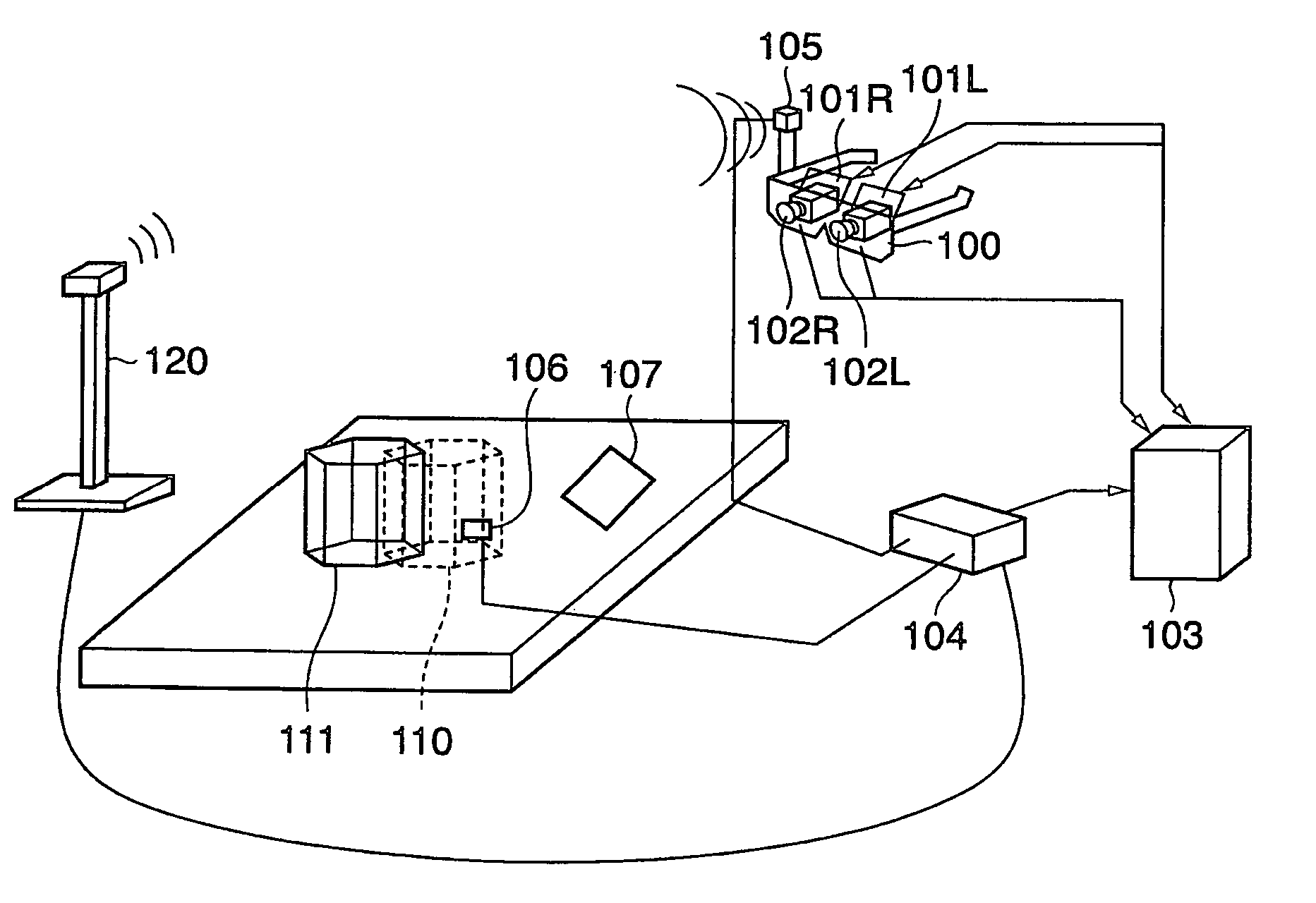
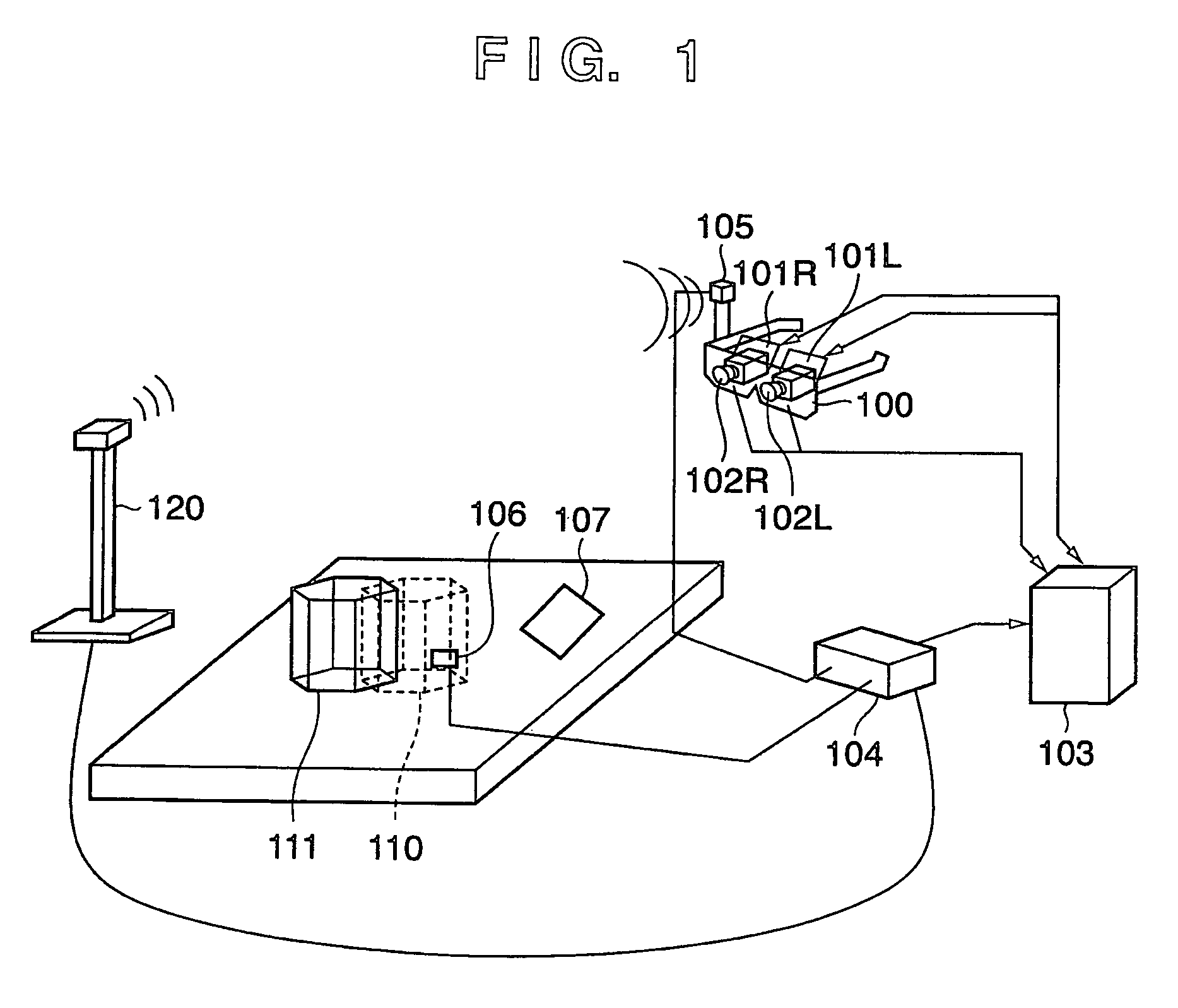
[0043]FIG. 1 shows an external view of a system which performs a process for providing an augmented-reality space generated by superimposing a virtual space on a physical space to an observer (user) according to an embodiment.

[0044] In FIG. 1, reference numeral 120 denotes a transmitter which generates a magnetic field. In this embodiment, a position and orientation measuring device such as FASTRAK (registered trademark) from Polhemus is used as the system for measuring positions and orientations. However, the essence of the following description is not limited to this. It will be appreciated from the following description that other techniques may be used in which such a device as a gyroscope is used to measure only the orientation and measure positional information and orientation drift errors from images.

[0045] Reference numeral 100 denotes a Head Mounted Display (hereinafter abbreviated as HMD) worn on the head of an observer for presenting a combination image of a physical sp...

second embodiment

[0144] In the first embodiment, multiple augmented-reality-space images generated are displayed at a time as shown in FIG. 7. In a second embodiment, augmented-reality-space images generated are displayed as moving images. In the GUI shown in FIG. 7, augmented-reality-space images of frames (at times t) are arranged and displayed at a time, whereas in the second embodiment images are displayed sequentially at the same position so that the augmented-reality-space images of frames are displayed as moving images.

[0145] To do so, the augmented-reality-space image currently generated is displayed at step S605 of the flowchart in FIG. 6 in a region where the previous augmented-reality-space image was displayed.

[0146] An operator can check a time lag in a comprehensive manner based on a larger number of augmented-reality-space images.

[0147] In some situations, it may be easier to evaluate a time lag using still images. Provision of the function of switching between still-image mode and ...

third embodiment

[0149] In a third embodiment, a computer 103 generates augmented-reality-space images and outputs them to a display device 101 and a display unit 1106. When an operator set a mode for performing a process for determining a lag (lag measurement mode), the computer 103 performs the processes shown in the flowcharts of FIGS. 4, 5, and 6 described with respect to the above embodiments.

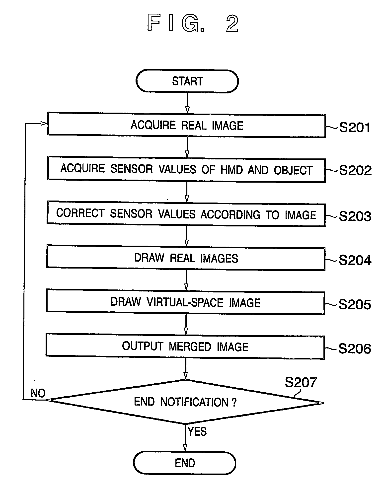
[0150]FIG. 9 is a flowchart of a process performed by a computer 103 according to the third embodiment. First, steps S201 to S206 of the flowchart in FIG. 2 are performed to generate augmented-reality-space images and output them to the display device 101 and the display unit 1106 (step S1101).

[0151] Then, determination is made as to whether the lag measurement mode is set by an operator of the computer 103 using a user operation unit 1104 (step S1102). As a result, if the lag measurement mode is not set, the process proceeds to step S1105, where determination is made as to whether the process should be ...


PUM


Abstract

On a captured image corresponding to acquisition time t of acquisition of the captured image, a virtual-space image based on the position and/or orientation at time that depends on the time t and a lag d is superimposed. An image on which the virtual-space image is superimposed is displayed. (S602-S606).

Description

FIELD OF THE INVENTION [0001] The present invention relates to a technology for superimposing an image in a virtual space on a physical space and presenting the resulting image. BACKGROUND OF THE INVENTION [0002] An augmented-reality system involves measuring the position of an operator's viewpoint, the direction of the operator's line of sight, and the position of an object in a space. One typical method used in systems for measuring the position and orientation uses a position and orientation measuring device such as FASTRAK (registered trademark) from Polhemus. Another known method uses such a device as a gyroscope to measure only the orientation and measures positional information and orientation drift errors from images. [0003] However, it is usually difficult to match the time at which an image in a physical space was acquired in a conventional augmented-reality system and the time at which the position and orientation measured by the position and orientation measuring device ...

Claims


Application Information

Patent Timeline
Patent Type & Authority Applications(United States)
IPC IPC(8): H04N7/14
CPCG06T19/006
Inventor MORITA, KENJISUZUKI, MASAHIROKATAYAMA, AKIHIROTANIMURA, KANAME
Owner CANON KK
Why Eureka
Try Eureka