
Apparatus and method for preventing call failure in an adaptive smart antenna system

a smart antenna and antenna technology, applied in diversity/multi-antenna systems, power management, wireless communication, etc., can solve problems such as error creation, phase mismatch, and phase mismatch calculation formula errors in the system itself, and achieve the effect of preventing a call failure for an ms and rapid increase in transmit power

Inactive Publication Date: 2006-11-02
SAMSUNG ELECTRONICS CO LTD
View PDF5 Cites 20 Cited by
  • Summary
  • Abstract
  • Description
  • Claims
  • Application Information

AI Technical Summary

Benefits of technology

[0013] An object of the present invention is to substantially solve at least the above problems and / or disadvantages and to provide at least the advantages described below. Accordingly, an object of the present invention is to provide an apparatus and method for preventing a call failure for an MS caused by a rapid increase in transmit power in response to a significant phase mismatch occurring within a phase mismatch correction cycle in a smart-antenna communication system.
[0014] Another object of the present invention is to provide an apparatus and method for preventing a call failure for an MS using a power control value, which is caused by a rapid increase in transmit power in response to a significant phase mismatch occurring within a phase mismatch correction cycle in a smart-antenna communication system.
[0015] The above objects are achieved by providing a transmitter and transmission method for preventing a call failure using a system power value, caused by rapidly increasing transmit power in response to a large phase mismatch occurring between a phase mismatch correction cycle in a smart-antenna communication system.

Problems solved by technology

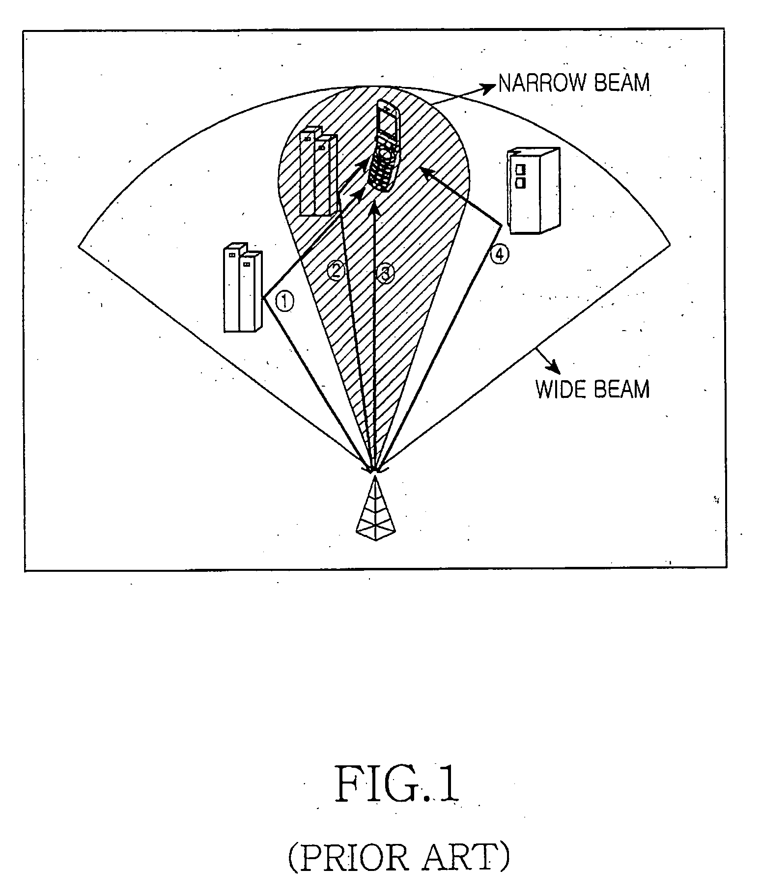
However, the smart-antenna communication system suffers phase mismatch. FIG. 1 illustrates a radio environment which causes phase mismatch to the smart-antenna communication system.
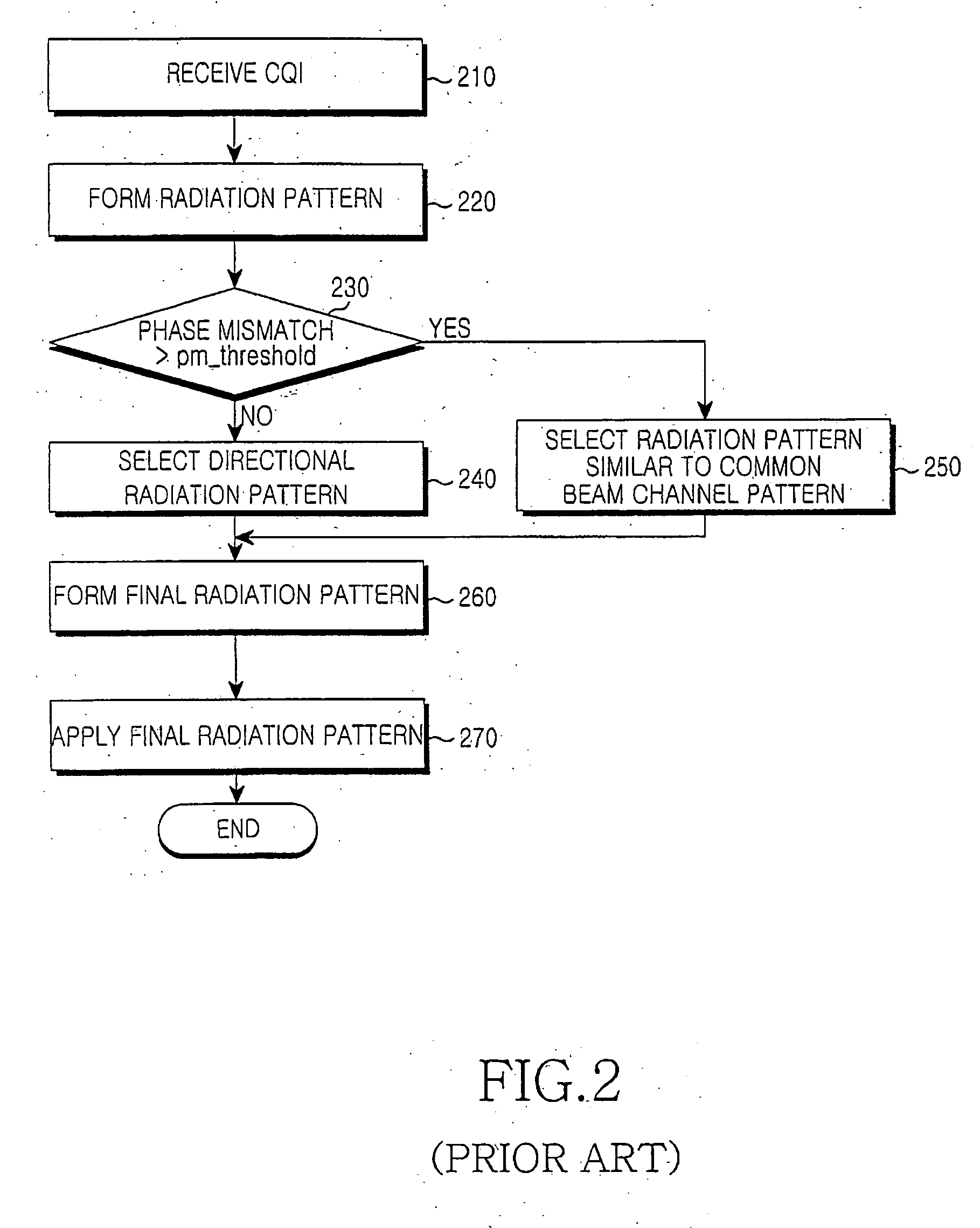
A distinctive shortcoming with this conventional phase mismatch correction is that only a particular radio channel environment among many radio channel environments is considered in a phase mismatch calculation formula and thus the phase mismatch calculation formula itself has errors.
In addition, there is an error caused by the difference between a power control time and a beamforming weight vector applying time.
In the case where power control is performed every 1.25 ms and the beamforming weight vector is changed every about 80 ms, an error can be created due to a channel environment change during resetting the beamforming weight vector and the difference between a channel generation time and a beamforming weight vector applying time.
Another problem arises from the difficulty of formulating the amount of power added to correct the phase mismatch, that is, the difficult quantification of the impact which the calculated phase mismatch imposes on actual system power control.
In case a significant channel change occurs in the course of applying the beamforming weight vector as illustrated in FIG. 3, the resulting beam does not reflect the channel change sufficiently.
In a rapidly changing radio channel environment facing the above-described problems, the phase mismatch is beyond an acceptable level for the MS.
Consequently, gain compensation is not effective through power control any more, and if the phase mismatch is kept uncorrected, the resulting high error rate leads to a call failure for the MS.
In this case, power control with no regard to phase mismatch may cause power control imbalance and interference to other MSs, as well.

Method used


Image

  • Apparatus and method for preventing call failure in an adaptive smart antenna system
  • Apparatus and method for preventing call failure in an adaptive smart antenna system
  • Apparatus and method for preventing call failure in an adaptive smart antenna system

Examples


Embodiment Construction

[0025] A preferred embodiment of the present invention will be described herein below with reference to the accompanying drawings. In the following description, well-known functions or constructions are not described in detail since they would obscure the invention in unnecessary detail.

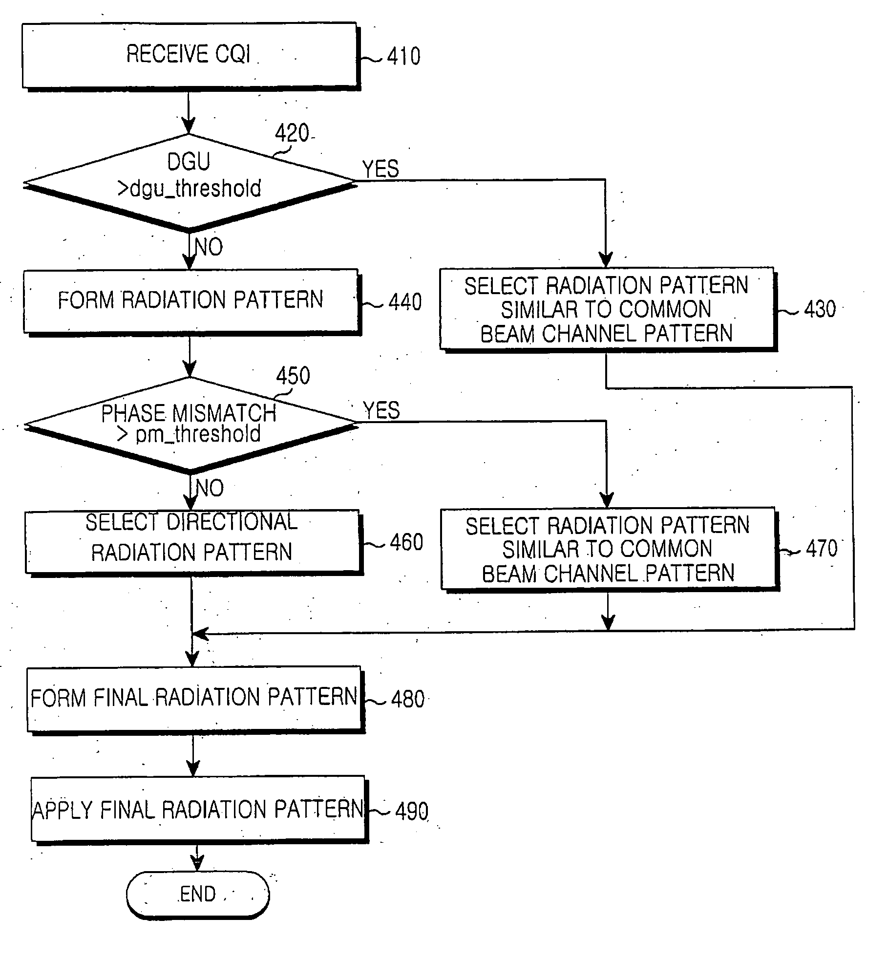
[0026] The present invention provides a transmitter and transmission method for preventing a call failure using a system power value, caused by rapidly increasing transmit power against a large phase mismatch occurring before a phase mismatch correction cycle elapses in a smart-antenna communication system. In the transmitter and transmission method, if the system power value is higher than a power threshold, a radiation pattern similar to a common beam channel pattern is created.

[0027] The following description is made in compliance with the cdma2000 Release C standard. A power value defined in this standard is utilized in forming a radiation pattern in a smart-antenna communication system. A powe...


PUM


Abstract

A transmitter and transmission method for preventing a call failure using a system power value, caused by rapidly increasing transmit power against a large phase mismatch occurring before a phase mismatch correction cycle elapses in a smart-antenna communication system. In the transmitter and transmission method, if the system power value is higher than a power threshold, a radiation pattern similar to a common beam channel pattern is created.

Description

PRIORITY [0001] This application claims priority under 35 U.S.C. § 119 to an application entitled “Apparatus And Method For Preventing Call Failure In An Adaptive Smart Antenna System” filed in the Korean Intellectual Property Office on Dec. 15, 2004 and assigned Serial No. 2004-106133, the contents of which are incorporated herein by reference. BACKGROUND OF THE INVENTION [0002] 1. Field of the Invention [0003] The present invention relates generally to a transmitter and transmission method for preventing a call failure for a Mobile Station (MS) using a power value, caused by increasing transmit power for the MS against a large phase mismatch occurring before a phase mismatch correction cycle elapses above an allowed transmit power in a smart-antenna communication system. In particular, the present invention relates to a transmitter and transmission method for forming a radiation pattern similar to a common beam (overhead) channel pattern if a system power level exceeds a power thr...

Claims


Application Information

Patent Timeline
IPC IPC(8): H04L1/02
CPCH04B7/0617H04B7/0632H04L1/203H04W52/04H04B7/0689H04B7/0626H04W52/42H04W52/241
Inventor RHA, SEOK-WANKWON, YOUNG-HOON
Owner SAMSUNG ELECTRONICS CO LTD
Learn More