Micro heat exchanger with thermally conductive porous network

a micro-heat exchanger and porous network technology, applied in the field of micro-heat exchangers, can solve the problems of limiting the implementation of such micro-heat exchangers to relatively expensive thermal control systems, relatively expensive and time-consuming conventional microfabrication techniques used to fabricate microchannels, etc., and achieves the effect of efficient and inexpensive manufactur

Active Publication Date: 2006-11-02
RTX CORP
View PDF13 Cites 98 Cited by
  • Summary
  • Abstract
  • Description
  • Claims
  • Application Information

AI Technical Summary

Benefits of technology

[0009] The present invention therefore provides a micro heat exchanger with multitudes of micro flow channels which are conducive to efficient and inexpensive manufacture.

Problems solved by technology

Although effective, conventional microfabrication techniques heretofore utilized to fabricate the microchannels are relatively expensive and time consuming which may limit implementation of such micro heat exchangers to relatively expensive thermal control systems.

Method used


Image

  • Micro heat exchanger with thermally conductive porous network
  • Micro heat exchanger with thermally conductive porous network
  • Micro heat exchanger with thermally conductive porous network

Examples


Embodiment Construction

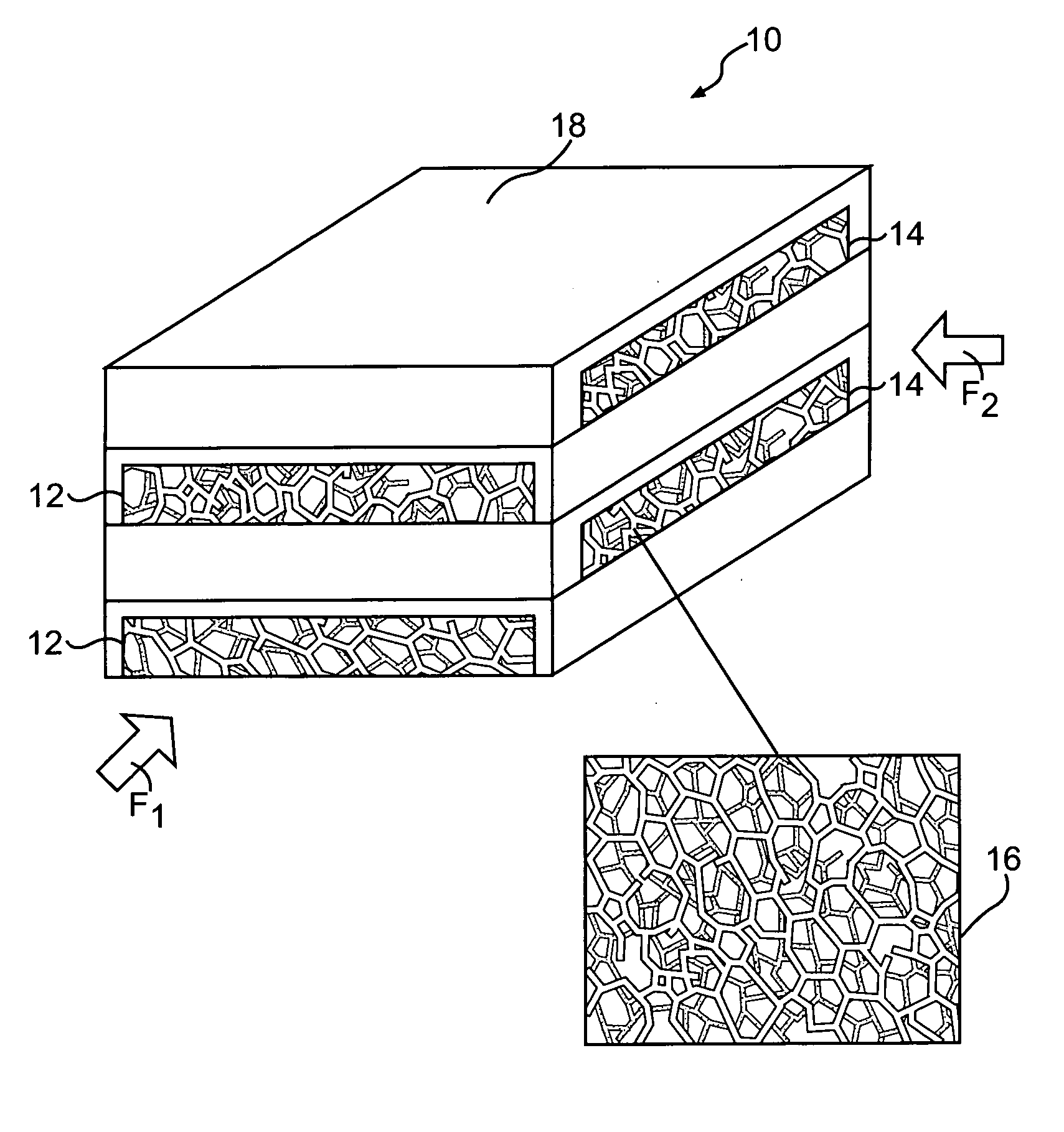
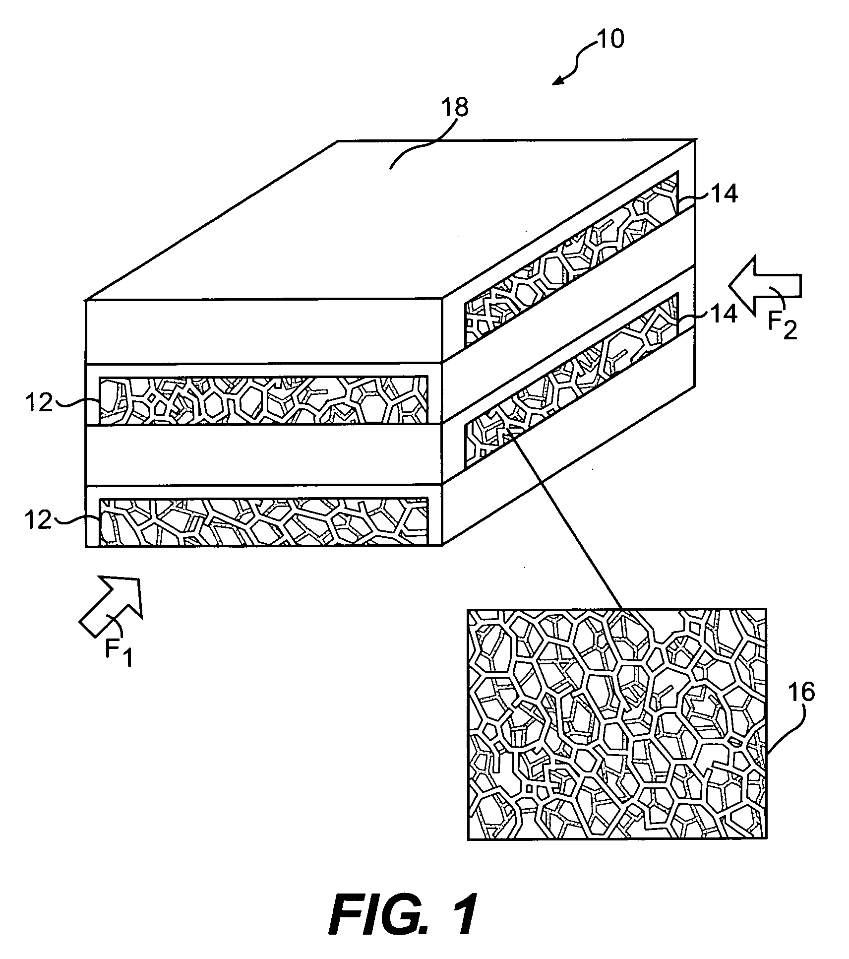
[0023]FIG. 1 illustrates a general perspective schematic view of a micro heat exchanger system 10. The term “micro heat exchanger system” as utilized herein is defined as a fluid-based thermal device where the surface area density ratio (ratio of surface area to volume) is 5,000 m2 / m3 or more. The microheat exchanger system 10 includes a first flow path 12 and a second flow path 14 transverse thereto for transferring thermal energy between a first fluid F1 flowing through the first flow path 12 and a second fluid F2 flowing through the second flow path 14. Although only two openings are illustrated for each of the first fluid F1 and the second fluid F2 in the disclosed embodiment, it should be understood that any number of paths will be usable with the present invention. That is, a sandwich structure of a multiple of interleaved serpentine paths as understood in a heat exchanger embodiment is a preferred flow path.

[0024] The first flow path 12 and the second flow path 14 are prefer...


PUM

PropertyMeasurementUnit
thickaaaaaaaaaa
thermal energyaaaaaaaaaa
thermally conductiveaaaaaaaaaa

Abstract

A micro heat exchanger system includes a first flow path and a second flow path transverse thereto for transferring thermal energy between a first fluid flowing through the first flow path and a second fluid flowing through the second flow path. The first flow path and the second flow path are filled with a thermally conductive porous network which incorporate unique structures, such as tubes, honeycomb, corrugated metal, reticulated foams, woven meshes or nonwoven mats or felts, engineered lattice structures, or a combination of these structures. In another embodiment, the thermally conductive porous network is coated with catalyst to provide an integrated heat exchanger and catalytic reactors.

Description

BACKGROUND OF THE INVENTION [0001] The present invention relates to a heat exchanger, and more particularly to a micro heat exchanger with microchannels formed by a thermally conductive porous network located within heat exchanger channels. [0002] Heat exchangers are used in a wide variety of industrial, commercial, aerospace, and residential settings. The function of many types of heat exchangers is to utilize a multitude of channels to transfer as much heat as possible from one fluid (usually a liquid) to another fluid (usually a gas) in as little space as possible, with as low a pressure drop (pumping loss) as possible. [0003] It is desirable to reduce the size of the heat exchanger needed for a given rate of heat exchange. As the heat exchangers structures shrink in size, i.e., as their surface area-to-volume ratio increases, thermal coupling between the structure and surrounding medium increases. The improved coupling is especially important for heat exchange between solid surf...

Claims


Application Information

Patent Timeline
Patent Type & Authority Applications(United States)
IPC IPC(8): B01J19/00
CPCB01J19/0093B01J19/249B01J35/04B01J37/0215B01J2219/00783B01J2219/00835F28F2260/02B01J2219/2453B01J2219/2458B01J2219/2462B01J2219/2465B01J2219/2479F28F13/003B01J2219/00873B33Y80/00
Inventor SCHMIDT, WAYDE R.
Owner RTX CORP
Why Eureka
Try Eureka