Battery pack

a battery pack and battery technology, applied in the field of batteries, can solve the problems of increasing the weight and cost of batteries, and achieve the effects of enhancing cell cooling performance, reducing weight and size, and reducing rigidity of end plates

Active Publication Date: 2006-11-02
TOYOTA JIDOSHA KK +1
View PDF9 Cites 66 Cited by
  • Summary
  • Abstract
  • Description
  • Claims
  • Application Information

AI Technical Summary

Benefits of technology

[0021] In the above configuration, the connecting members are preferably arranged on both sides of each of the cells of the battery modules, so that the end plates are restrained at both sides of each cell, whereby the rigidity of the end plates is made lower, leading to weight and size reductions.
[0022] Heat dissipation fins forming the cooling medium passages may be provided on the long side faces of the cells to enhance the cell cooling performance.
[0023] The spacer portions may have projections that abut on the long side faces of the cells to form the cooling medium passages, so that cooling medium passages

Problems solved by technology

In a battery pack of the above configuration, however, the end plates, as a restraining tool, need to have a rigidity that is high enough to withstand the internal pressure of the prismatic cel

Method used


Image

  • Battery pack
  • Battery pack
  • Battery pack

Examples


Embodiment Construction

[0036] One embodiment of the battery pack of the present invention will be hereinafter described with reference to FIG. 1 to FIG. 7 and FIG. 9.

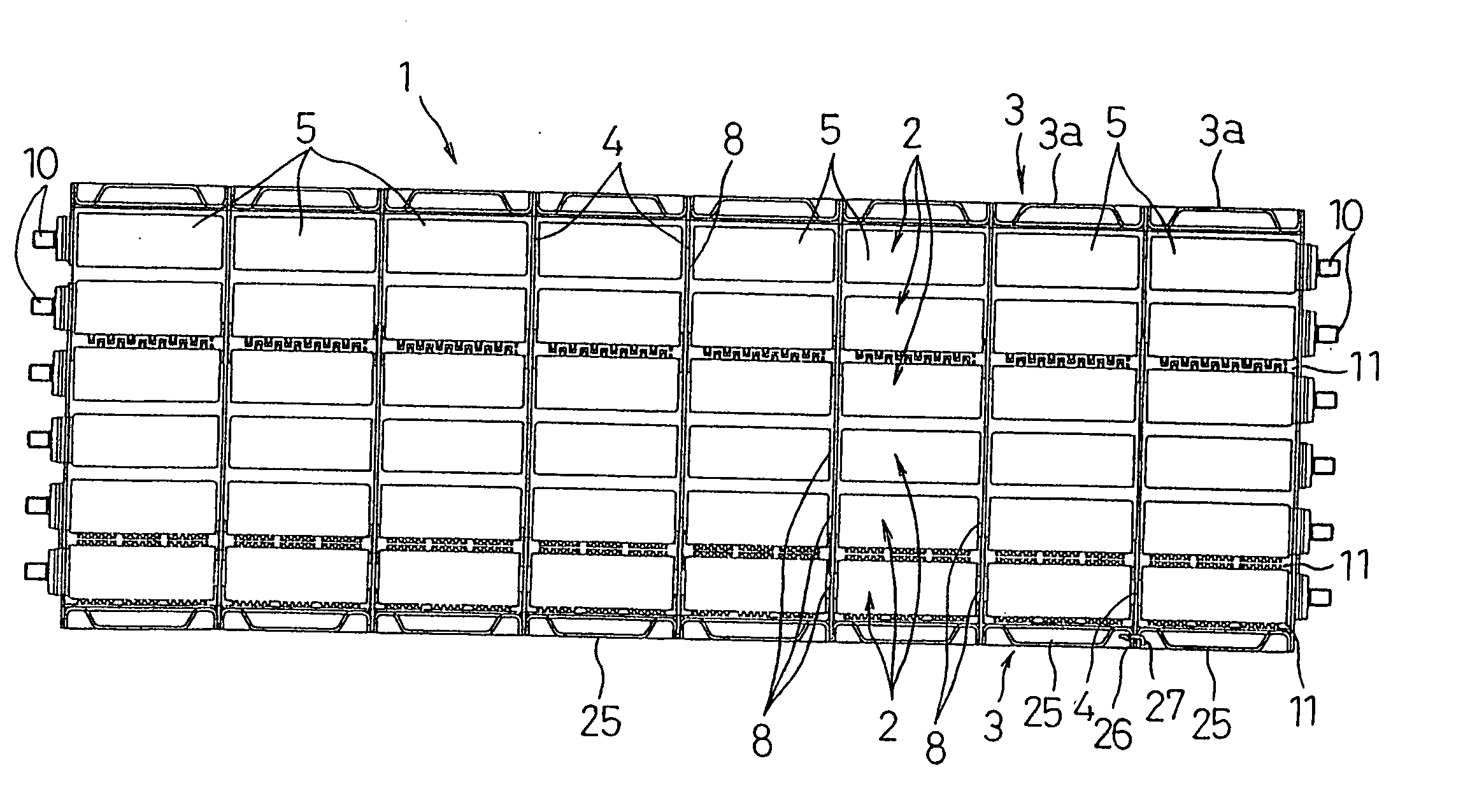
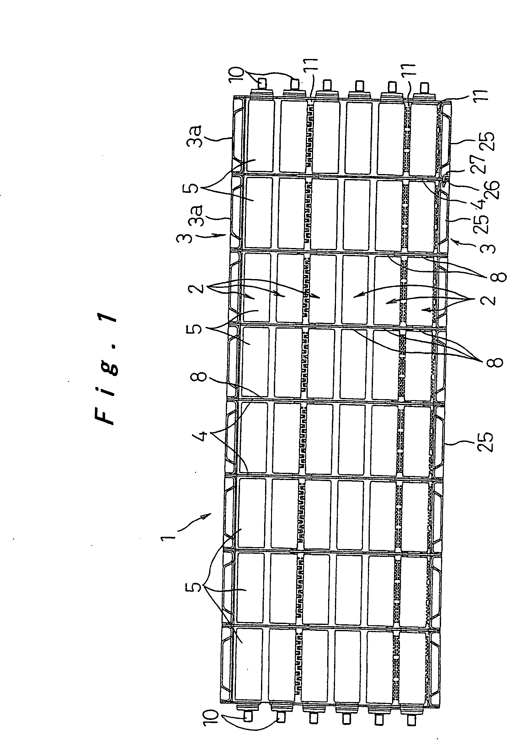
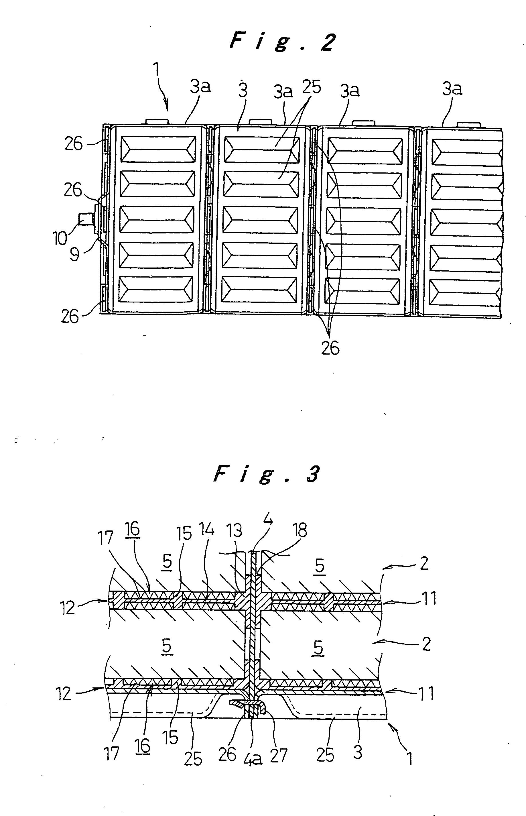
[0037] In FIG. 1 to FIG. 4, 1 denotes a battery pack used as a drive power source of electric vehicles including electric vehicles, hybrid vehicles or the like driven by fuel batteries. A plurality of (six in the illustrated example) battery modules 2 are arranged in parallel, and end plates 3 are arranged at both ends in the parallel alignment direction of the battery modules 2. The end plates 3 are coupled together using a plurality of plate strips or connecting members 4 (three each at nine locations in the illustrated example).

[0038] The battery module 2 consists of a plurality of (eight in the illustrated example) cells 5. Each cell 5 is formed by accommodating elements for electromotive force consisting of laminated positive and negative electrode plates with separators interposed therebetween and liquid electrolyte in a prismatic met...


PUM


Abstract

The battery pack uses a restraining tool capable of secure restraint despite relatively low rigidity to achieve weight and cost reductions. The battery pack is formed of a plurality of parallel arranged battery modules (2), each consisting of a plurality of cells (5) electrically connected in series and coupled together in one piece with gaps (8) formed therebetween (5, 5), each cell being formed of elements for electromotive force encased in a prismatic case. The restraining tool includes connecting members (4) extending through the gaps (8) at both ends of the parallel arranged battery modules (2) and between two given cells (5, 5).

Description

TECHNICAL FIELD [0001] The present invention relates to a battery pack formed of a plurality of parallel arranged battery modules, each battery module consisting of a plurality of series-connected cells. BACKGROUND ART [0002] There have been known battery packs having large power capacity, in which a plurality of prismatic cells, or battery modules, each consisting of a plurality of cells connected in series and coupled together in one piece, are arranged parallel with insulating spacers interposed therebetween. End plates are arranged at both ends in the direction of alignment of the cells or battery modules and tightly fastened with a restraining rod or a band, so as to prevent expansion of side faces of the cells or battery modules due to internal pressure of batteries. The cells or battery modules are connected either in series or in parallel (see, for example, Japanese Patent Laid-Open Publication No. 11-126585 and Published Japanese Translation No. 2001-507856 of PCT Internati...

Claims


Application Information

Patent Timeline
IPC IPC(8): H01M10/50H01M2/10H01M10/60H01M10/613H01M10/625H01M10/647H01M10/6551H01M10/6557H01M10/6563H01M50/209H01M50/262H01M50/291
CPCH01M2/1072H01M2/1077H01M10/5004H01M10/5059H01M10/5032H01M10/5046H01M10/5016H01M10/625H01M10/647H01M10/6551H01M10/6557H01M10/613Y02E60/10H01M50/209H01M50/291H01M50/262
Inventor HAMADA, SHINJIASAHINA, TAKASHISUNAGAWA, YOSHITAKAETO, TOYOHIKO
Owner TOYOTA JIDOSHA KK
Why Eureka
Try Eureka