Mobile device and method of adjusting a power measurement period of a received cell signal

a technology of a mobile device and a power measurement period, applied in the field of mobile communications, can solve the problems of mobile devices consuming a predetermined amount of power, power measurement process performed by modules consuming a significant amount of power, and power measurement process for cell monitoring consuming battery power of mobile devices

Inactive Publication Date: 2006-11-02
SAMSUNG ELECTRONICS CO LTD
View PDF11 Cites 31 Cited by
  • Summary
  • Abstract
  • Description
  • Claims
  • Application Information

AI Technical Summary

Benefits of technology

[0027] Various embodiments of the present invention provide mobile devices (e.g., cell-phones) capable of var

Problems solved by technology

Meanwhile, in order to perform the power measurement process, modules such as an RF processing circuit, a baseband modem and a microprocessor included within the mobile device consume a predetermined amount of power.
When the mobile device is in the “standby” mode, the power measurement process performed by the modules consumes a significant amount of power.
Accordingly, the power measurement process for the cell monitoring consumes battery power of the mobile device even in the

Method used


Image

  • Mobile device and method of adjusting a power measurement period of a received cell signal
  • Mobile device and method of adjusting a power measurement period of a received cell signal
  • Mobile device and method of adjusting a power measurement period of a received cell signal

Examples


example embodiment 1

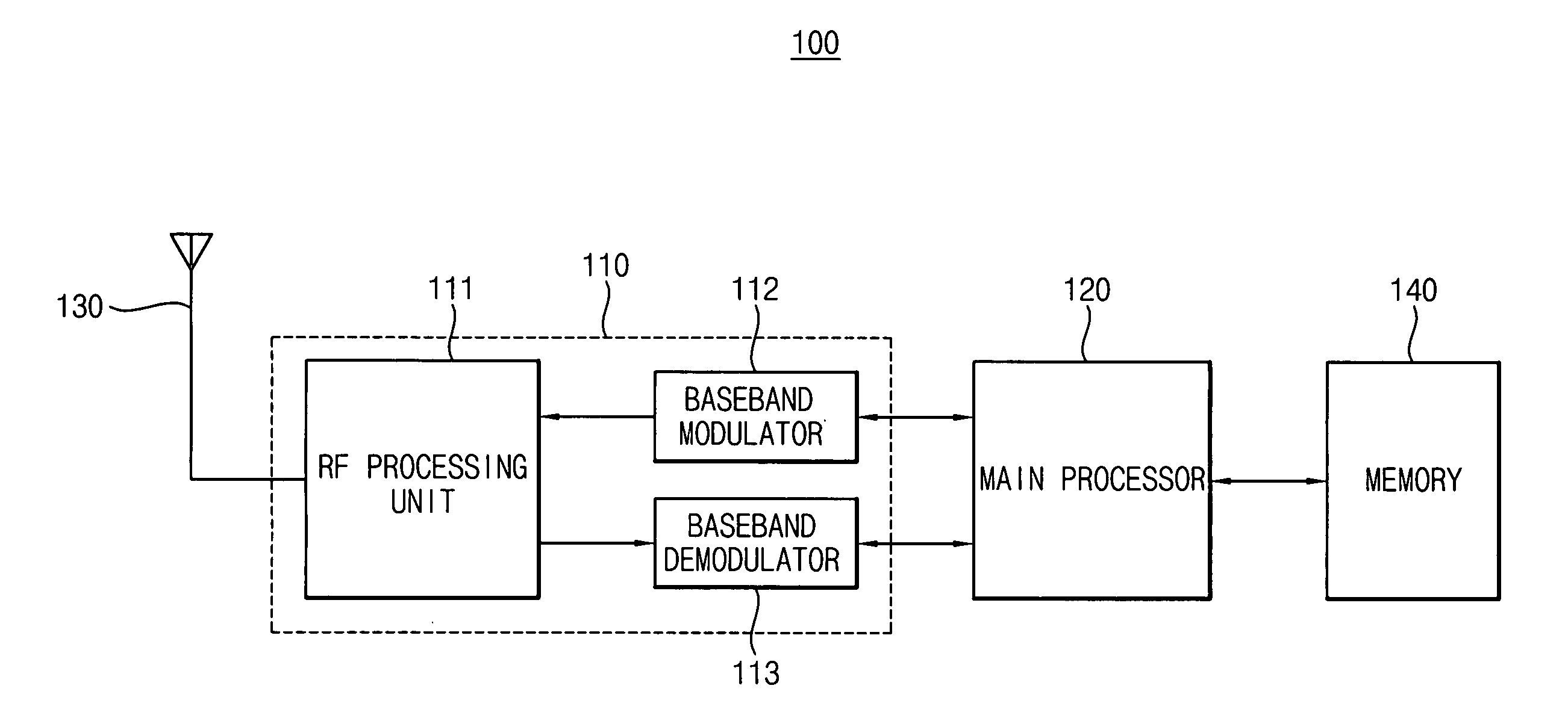
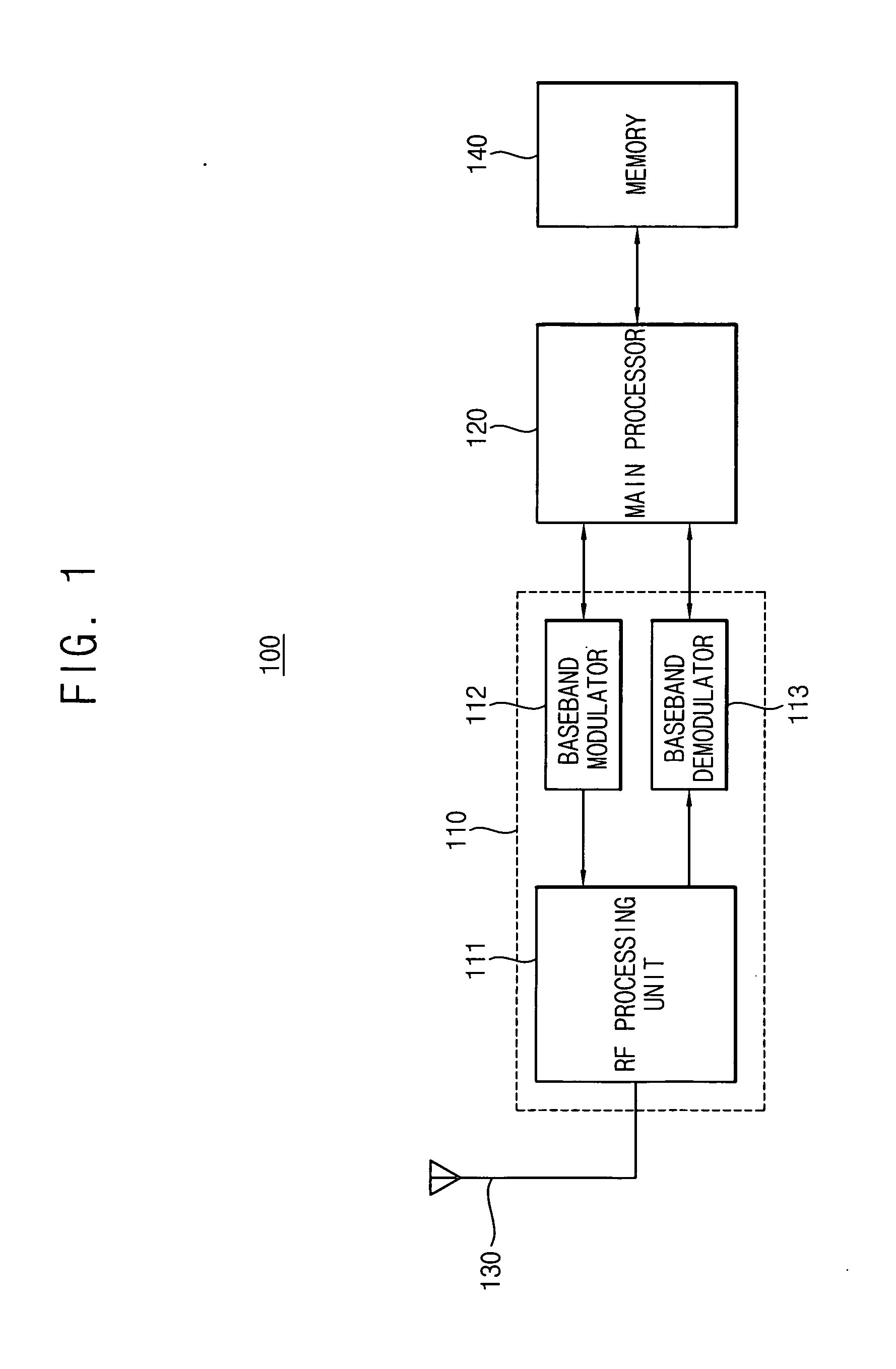
[0067]FIG. 1 is a block diagram of a mobile device (e.g., cell-phone) 100 according to an example embodiment of the present invention.

[0068] Referring to FIG. 1, the mobile device 100 includes an antenna 130, a signal processing unit 110, a main processor 120 and a memory 140.

[0069] Of course, the mobile device 100 (e.g., a cell phone) additionally includes usual elements such as a microphone, a speaker, a liquid crystal display, a keypad and so on; however, for the sake of brevity, only elements associated with illustrating the features present invention will be illustrated and described, and other elements will be omitted.

[0070] The antenna 130 transmits / receives radio frequency (RF) signals to / from a base station. More particularly, the antenna 130 receives a plurality of cell signals, that is, a “paging blocks,” from a serving cell and from neighboring cells to transmit the received cell signals to the signal processing unit 110. Additionally, the antenna 130 transfers a radi...

example embodiment 2

[0105]FIG. 3 is a block diagram of a mobile device 200 according to another example embodiment of the present invention.

[0106] Referring to FIG. 3, the mobile device 200 includes an antenna 130, a signal processing unit 110, a memory 240, a power measurement period generation module 250 and a control module 220. Of course, the mobile device 200 further includes usual elements such as a microphone, a speaker, a liquid crystal display device, a keypad and so on; however, for the sake of brevity, in FIG. 3 and the second example embodiment of the present invention, only elements associated with important points of the present invention will be illustrated and described, and other elements not associated with the important points of the present invention will be omitted.

[0107] The antenna 130 and the signal processing unit 110 included in the mobile device 200 of FIG. 3 have a configuration and functions identical to those included in the mobile device 100 of FIG. 1, respectively.

[01...


PUM


Abstract

A mobile device includes an antenna, a signal processing unit and a main processor. The mobile device increases or re-initializes the variable power measurement period based on the occurrence or frequency of cell reselections, rather than relying upon GPS information. The signal processing unit processes RF cell signals received via the antenna. The main processor enables (wakes up) the signal processing unit to measure each power level of the received cell signals and adjusts the power measurement period based on the current actual cell reselection frequency (e.g., comparing the current actual cell reselection frequency with a predetermined cell reselection mean frequency, e.g., in a standby mode). The signals include cell signals received from each base station of a corresponding serving cell and of neighboring cells.

Description

CLAIM FOR PRIORITY [0001] This application claims priority under 35 U.S.C. §119 of Korean Patent Application No. 2005-36400 filed on Apr. 29, 2005 in the Korean Intellectual Property Office, the entire contents of which are herein incorporated by reference. BACKGROUND OF THE INVENTION [0002] 1. Field of the Invention [0003] The present invention relates to the field of mobile communications and more specifically to a mobile communication device (e.g., cell phone) capable of variably adjusting a power measurement period of a cell signal so as to monitor and select an appropriate cell among a currently serving cell and neighboring cells, and a method of adjusting a power measurement period of a cell signal therein. [0004] 2. Description of the Related Art [0005] In mobile communication systems (e.g., cell phones), a multiple access technique is generally employed so that a plurality of independent information may be transferred through a common channel, and examples of multiple access...

Claims


Application Information

Patent Timeline
IPC IPC(8): H04Q7/20H04W48/20
CPCY02B60/50H04W48/20Y02D30/70H04W88/02
Inventor RYU, KIL-HYEN
Owner SAMSUNG ELECTRONICS CO LTD
Why Eureka
Try Eureka