
Hybride 3D path router

a router and hybrid technology, applied in the field of hybrid 3d path routers, can solve the problems of inability to generate a technique, inability to use a pipe routing method in congested areas, and difficulty in routing pipes, ducts and other services in three dimensions (3d)

Inactive Publication Date: 2006-11-02
INDAL PLANNING TECH
View PDF15 Cites 55 Cited by
  • Summary
  • Abstract
  • Description
  • Claims
  • Application Information

AI Technical Summary

Benefits of technology

[0013] A primary objective of the present invention is to provide a computer aided design system and method which combines high speed real-time two dimensional router software and a simple graphical user interface to create an environment in which a designer can rapidly create fully valid 3D(three dimensional) routes for piping, HVAC(Heating, Ventilation and Air Conditioning) ducting , cableways and other swept shapes.
[0016] A fourth objective of the present invention is to provide a computer based method and system that can provide optimal 3D routes in congested areas such as those found in ships, aircraft and vehicles, and the like, and are not limited to rectilinear paths.
[0028] The step of calculating 2D(two dimensional) slices through a 3D(three dimensional) world for the guide path, can further include the step of generating a guidance cost function for the router by using a diffusion operator on the bit map image of the objects to be avoided.

Problems solved by technology

The routing of pipes, ducts, and other services in three dimensions (3D) through congested areas, is difficult, even using the best available commercial 3D computer aided design (CAD) systems.
The CAD systems allow the designer to view the geometry from a variety of directions, and may tell the designer after the fact if the route that has been input is invalid because it would cause the pipe or duct or other service to pass through some fixed object, such as a piece of equipment.
What CAD systems do not do is provide any guidance to the designer on where to place the route.
In the congested areas found in ships and vehicles, non-rectilinear routes are required, which this technique cannot generate.
These routers are all limited to rectilinear paths, and are thus not capable of being used for pipe routing in congested areas such as in ships and vehicles.
Further, they do not address the harder problem of routing more complex shapes such as heating, ventilation and air conditioning (HVAC) ducts.
That approach requires that the designer already have a rough 3D route, and requires significant labor by the designer to input a set of constraints.
Further, the approach used by Drumheller does not address more complex shapes, such as HVAC ducting and cableways.
As with other automatic routing techniques, the computational complexity of the problem being solved by Drumheller is such that solution times are in minutes, which makes it unsuitable for interactive design tool environments where real time feedback is needed.
In general, the prior art solutions suffer from various problems.
Current solutions generally take minutes or hours to compute path routes, prohibiting them from being imbedded directly in an interactive design tool.
Most current solutions are limited to rectilinear paths, and are thus not capable of being used in the congested areas typical of ships and vehicles.

Method used


Image

  • Hybride 3D path router
  • Hybride 3D path router
  • Hybride 3D path router

Examples


Embodiment Construction

[0061] Before explaining the disclosed embodiments of the present invention in detail, it is to be understood that the invention is not limited in its applications to the details of the particular arrangements shown since the invention is capable of other embodiments. Also, the terminology used herein is for the purpose of description and not of limitation.

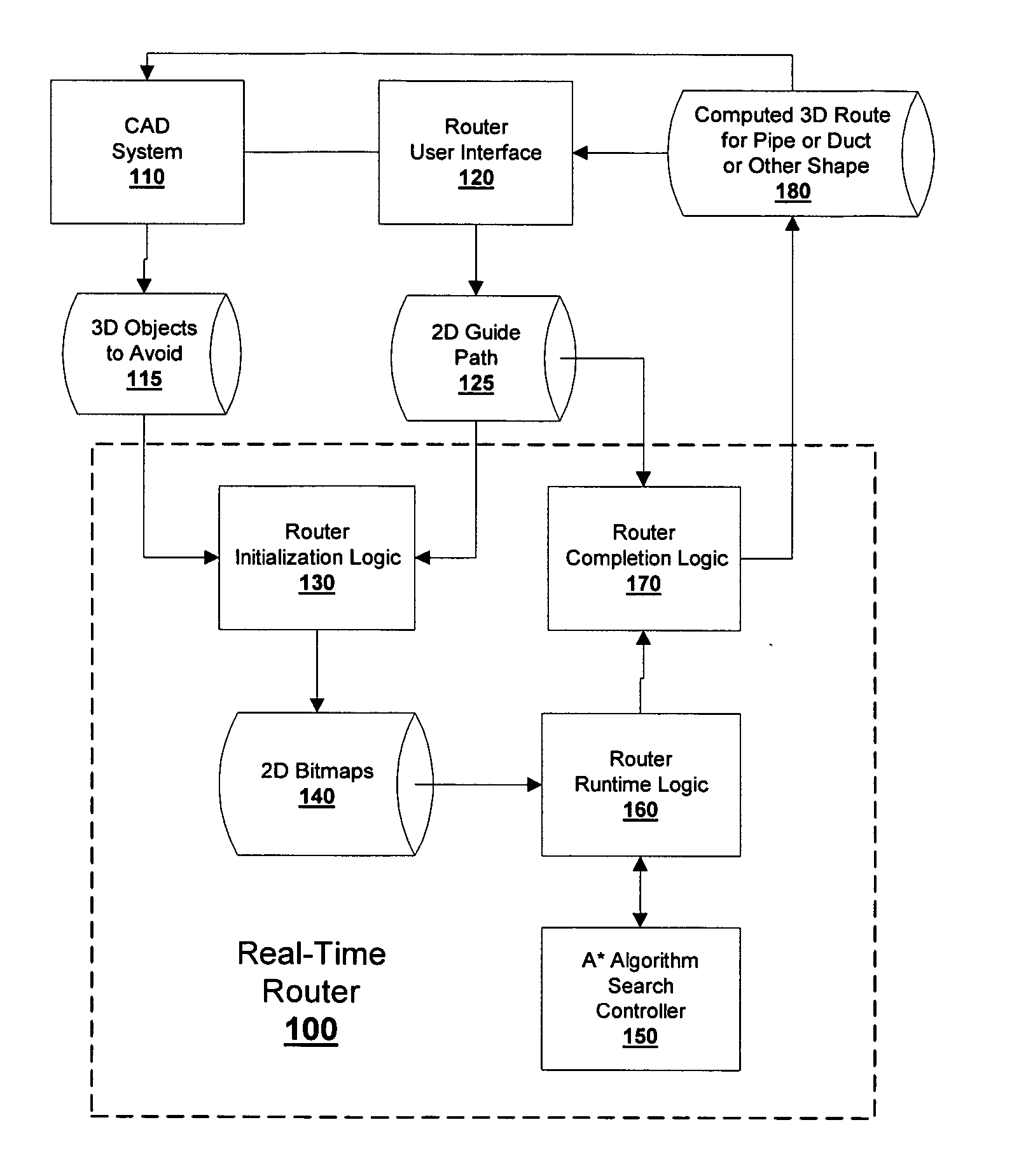
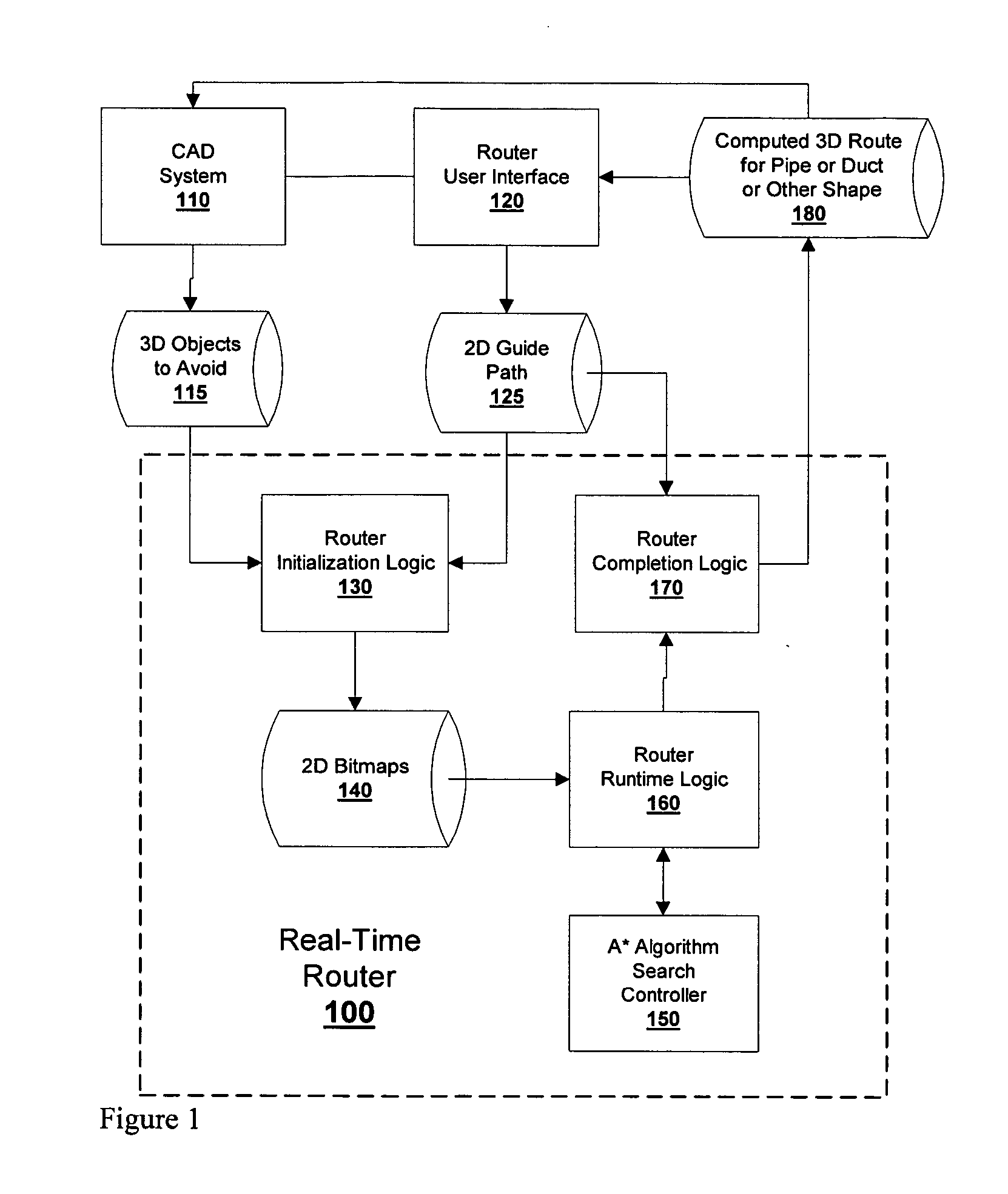
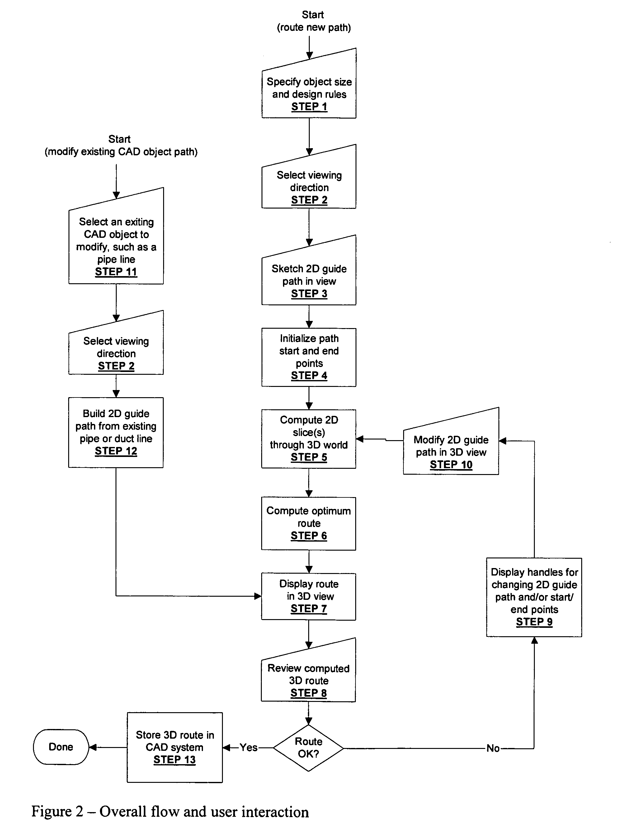
[0062]FIG. 1 is a block diagram of the major components of the Hybrid 3D Path Router that can include Real-Time Router 100, CAD system 110, 3D Objects to Avoid 115, Router User Interface 120, 3D Guide Path 125, Router Initialization Logic 130, 2D Bitmaps 140, A* Algorithm Search Controller 150 (described in reference to FIG. 22), Router Runtime Logic 160, and Router Completion Logic 170. FIG. 2 is a flow chart of overall flow and user interaction of the Hybrid 3D Path Router shown in FIG. 1. The router may be used to create new 3D paths, or to modify existing 3D paths. FIG. 2 is a combined flow chart which shows the data flow and...


PUM


Abstract

Computer aided design(CAD) methods and systems of routing pipes, ducts and other services, such as utility and HVAC(Heating Ventilation and Cooling) lines in three dimensions(3D) through congested areas in industrial plants, ships, land vehicles, air vehicles, structures, buildings, and the like. The invention combines high speed real-time two dimensional router software and a simple graphical user interface to create an environment in which a designer can rapidly create fully valid 3D(three dimensional) routes for piping, HVAC(Heating, Ventilation and Air Conditioning) ducting, cableways and other swept shapes. The designer can use the invention to generate optimal 3D routes nearly as fast as the designer can move his / her mouse, and the invention can be imbedded within existing 3D(three dimensional) CAD(computer aided design) systems.

Description

[0001] This invention claims the benefit of priority to U.S. Provisional Patent Application Ser. No. 60 / 676,042 filed Apr. 29, 2005.FIELD OF INVENTION [0002] This invention relates to computer aided design (CAD) methods and systems for the routing of conduits, namely pipes, ducts and other services, in three dimensions(3D) through congested areas in industrial plants, ships, land vehicles, aircraft and structures. BACKGROUND AND PRIOR ART [0003] The routing of pipes, ducts, and other services in three dimensions (3D) through congested areas, is difficult, even using the best available commercial 3D computer aided design (CAD) systems. Current practice is to manually draft the routes using a 3D CAD system. The CAD systems provide the designer with tools for performing geometrical constructions, such as placing lines and arcs in space, and defining the lines and arcs to be the path for a pipe, duct, or other service. The CAD systems allow the designer to view the geometry from a varie...

Claims


Application Information

Patent Timeline
Patent Type & Authority Applications(United States)
IPC IPC(8): G06F17/50
CPCG06F17/5004G06F2217/34G06F17/5095G06F17/509G06F30/13G06F30/15G06F30/18G06F2113/14
Inventor ROURKE, PATRICK W.
Owner INDAL PLANNING TECH
Learn More