Pedestal structure for raised access floors

a technology for access floors and pedestals, which is applied in the direction of building roofs, constructions, building components, etc., can solve the problems of difficult recovery, damage to the surface of floors, and the intertwining of lines becomes more and more complicated, so as to increase the leveling accuracy

Inactive Publication Date: 2006-11-09
CHEN YAO CHUNG +1
View PDF5 Cites 54 Cited by
  • Summary
  • Abstract
  • Description
  • Claims
  • Application Information

AI Technical Summary

Benefits of technology

[0013] A primary objective of the present invention is to provide a pedestal structure for raised access floors, the pedestal structure needs not to be stuck on the ground and thereby will not damage the existing ground structure, and can be recovered for reusing.
[0014] Another objective of the present invention is to provide a pedestal structure for raised access floors. After assembling, the heights of pedestals can be directly adjusted on the floors without lifting the floors, this can largely increase the accuracy of leveling of the floors.
[0015] To achieve the above stated objectives, the pedestal structure for raised access floors of the present invention comprises: a supporting seat, a fixing seat and a socket set screw. Wherein the supporting seat has on the top thereof a screw bolt which is connected on its bottom with a bottom seat; The bottom seat has a protruding portion having centrally a pivot hole, the bottom of the screw bolt is in a shape of “H” for the purpose of connecting into the pivot hole. While the fixing seat has a through hole for connecting by screwing with the screw bolt to raise the fixing seat; the screw bolt has on the top thereof a hexagonal adjusting hole for engaging therein a hexagonal wrench to adjust the height of the fixing seat relative to the supporting seat. The fixing seat is provided with a plurality of recessed portions for placing a raised access floor on and fixedly connecting with them. The socket set screw is connected by screwing into the through hole of the fixing seat; thereby the heights after screw connecting of the fixing seat and the supporting seat can be fixed.

Problems solved by technology

Because each computer can only be connected or electrically connected with other computers through a network, intertwining of lines becomes more and more complicated when amount of equipment gets larger and larger.
If in an office lines are exposed outside, they not only look ugly, but also affect walking of workers.
However, detachment of the pedestals A10 afterwards may still leave traces of glue when in moving to another working field, changing assembling or being necessary to change the electric lines in the floors, the surfaces of the floors have been damaged and are hard to be recovered.
This really is a problem for the business of field rent-service or for offices users nowadays.
And more, the bottoms A12 of the pedestals A10 after detachment will have residual traces of glue to make the pedestals A10 no more being usable, thus wastes of resources as well as cost can be induced.
Thus the floors after laying out is not be truly horizontal but look uneven.
The process of work induces over working time, and inconvenience of working.
However, although the technique is designed to get the object of adjusting the level of the floor B10, when in assembling and using practically, by the fact that the adjustment can only be performed after detachment of the screw B23 and removing the square cover B24, the supporting seat B14 likewise needs to be fixed on the ground in favor of rotating and adjustment, this is inconvenient and still has room for improvement as to the whole designing and using.

Method used


Image

  • Pedestal structure for raised access floors
  • Pedestal structure for raised access floors
  • Pedestal structure for raised access floors

Examples


Embodiment Construction

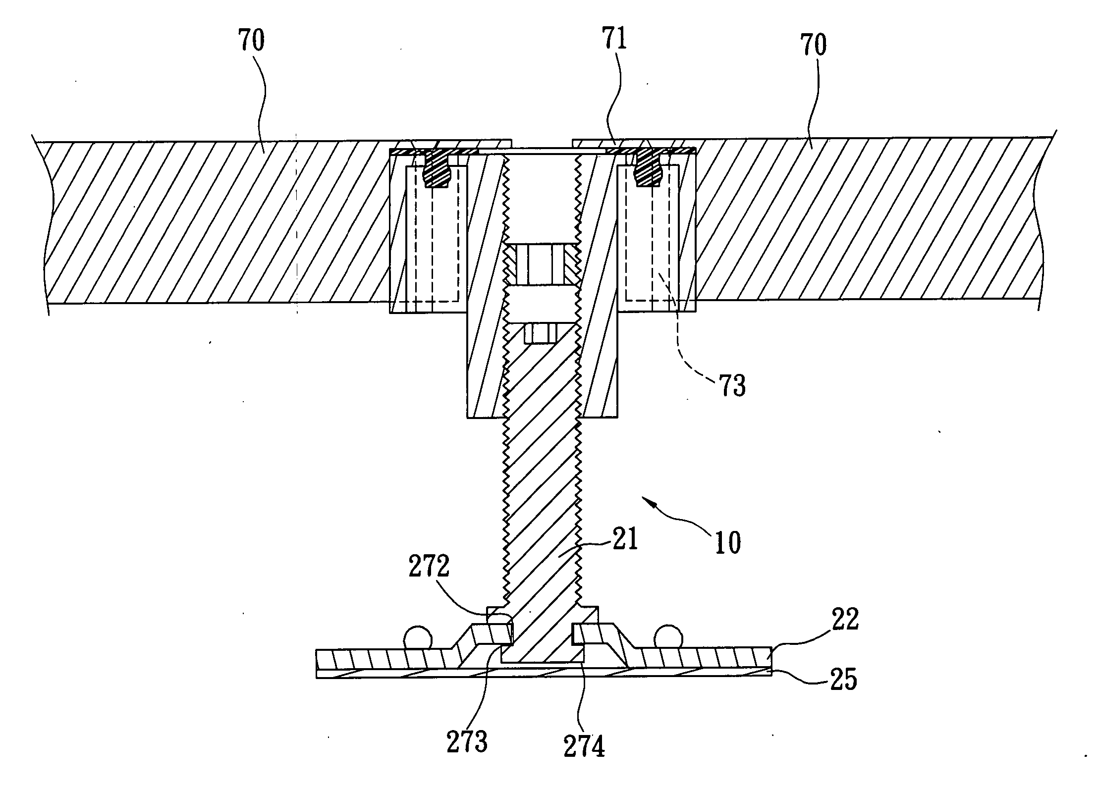
[0029] Referring firstly to FIGS. 2-3B showing perspective views and schematic sectional views of a preferred embodiment of a pedestal 10 of the present invention, the pedestal 10 comprises: a supporting seat 20, a fixing seat 30 and a socket set screw 40.

[0030] Wherein the supporting seat 20 has on the top thereof a screw bolt 21 which is connected on its bottom with a bottom seat 22; the supporting seat 20 basically is metallic and has sufficient strength. The screw bolt 21 has on the top thereof a hexagonal adjusting hole 23; the bottom of the screw bolt 21 is in a shape of “H”. The bottom seat 22 has a protruding portion 27 with a pivot hole 271 to have the bottom of the screw bolt 21 can be pivotally connected with the pivot hole 271. The pivot hole 271 has a slightly larger diameter, in order that small gaps 272, 273 are formed between the “H” shaped bottom of the screw bolt 21 and the pivot hole 27. The bottom seat 22 has thereon a plurality of openings 24, further has on it...


PUM


Abstract

A pedestal structure for raised access floors comprising: a supporting seat, a fixing seat and a socket set screw, wherein the supporting seat has on the top thereof a screw bolt which is connected on its bottom with a bottom seat, the bottom seat has a protruding portion having centrally a pivot hole, the bottom of the screw bolt is in a shape of “H” for the purpose of connecting into the pivot hole; while the fixing seat has a through hole for connecting by screwing with the screw bolt to raise the fixing seat; the screw bolt has on the top thereof a hexagonal adjusting hole for engaging therein a hexagonal wrench to adjust the height of the fixing seat relative to the supporting seat. The fixing seat is provided with a plurality of recessed portions for placing a raised access floor on and fixedly connecting with them. The socket set screw is connected by screwing into the through hole of the fixing seat; thereby the heights after screw connecting of the fixing seat and the supporting seat can be fixed. The structure is applicable to use for a network-line or pipeline laying out for raised access floors in a house, a building and a school etc.

Description

BACKGROUND OF THE INVENTION [0001] 1. Field of the invention [0002] The present invention relates to a pedestal structure for raised access floors, and more particularly to a pedestal structure non-sticking to the ground and able to adjust its height immediately before or after assembling, the structure can largely reduce working hours in construction, and increase flexibility of changing wires, changing arrangement and moving of the raised access floors, it is applicable to use for a network-line or pipeline laying out for raised access floors in a house, a building, a school or an short-term exhibition field etc. [0003] 2. Description of the Prior Art [0004] For those working places widely using computers, distribution and laying-out of networks and other kind of lines are very important and necessary. Because each computer can only be connected or electrically connected with other computers through a network, intertwining of lines becomes more and more complicated when amount of ...

Claims


Application Information

Patent Timeline
Patent Type & Authority Applications(United States)
IPC IPC(8): E04B1/00E04B5/00
CPCE04F15/02476
Inventor CHEN, YAO-CHUNGWANG, SHIH-JAN
Owner CHEN YAO CHUNG
Why Eureka
Try Eureka