Thermally insulated structure - full depth sandwich joint concept

Active Publication Date: 2006-11-09
NORTHROP GRUMMAN SYST CORP
View PDF10 Cites 16 Cited by
  • Summary
  • Abstract
  • Description
  • Claims
  • Application Information

AI Technical Summary

Benefits of technology

[0011] The present invention specifically addresses the above-referenced needs associated with composite joints. More specifically, the present invention is a composite joint which minimizes heat conduction between an exterior and an interior of the composite joint. In this regard, the composite joint of the present invention may be configured to limit heat conduction in a specified direction across the composite joint. For example, the composite joint may be configured to

Problems solved by technology

For core panels made of closed cell foams, conductive heat transfer is made difficult due to the large number of small cells that the heat must cross in traveling from one face sheet to another face sheet, such as from an outer face sheet to an inner face sheet.
Control of heat flow in joint areas is more difficult due to the heat path provided by mechanical fastener

Method used


Image

  • Thermally insulated structure - full depth sandwich joint concept
  • Thermally insulated structure - full depth sandwich joint concept
  • Thermally insulated structure - full depth sandwich joint concept

Examples


Embodiment Construction

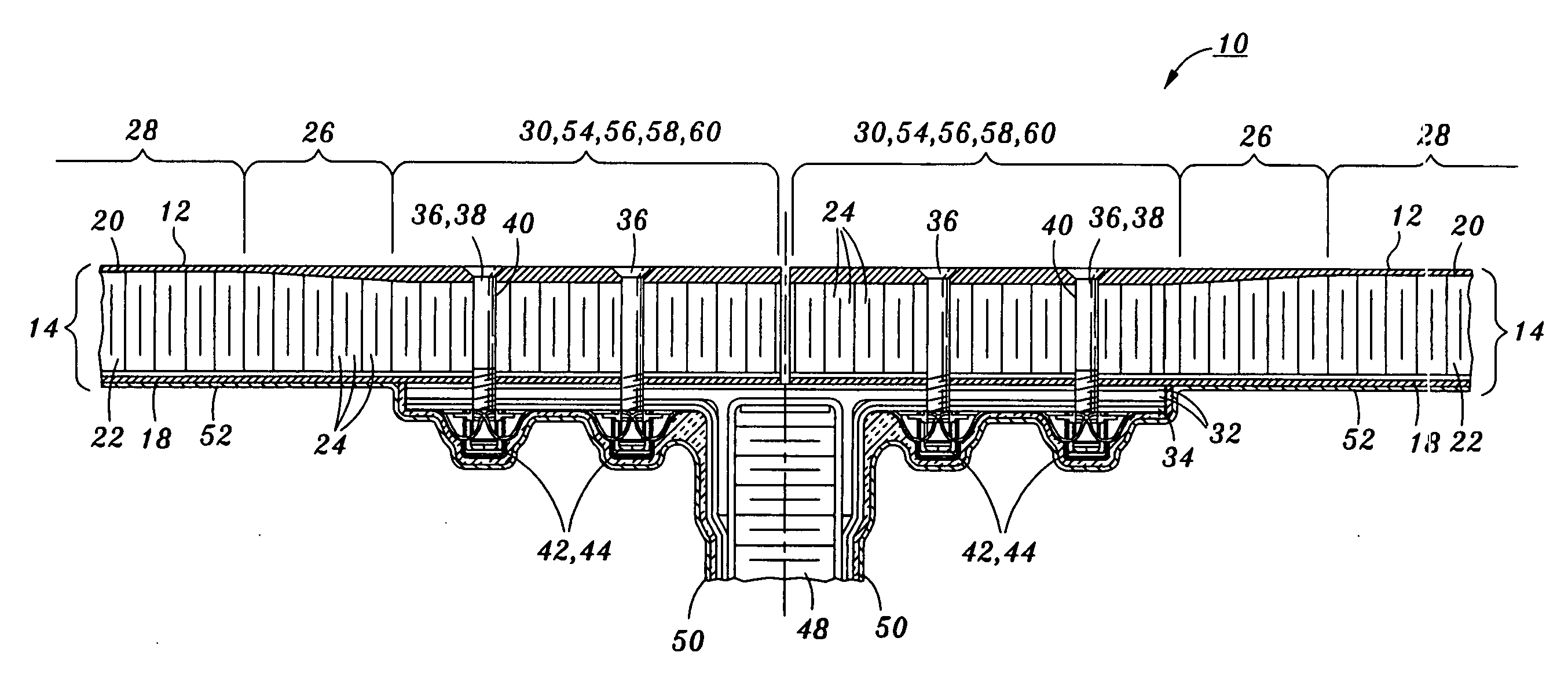
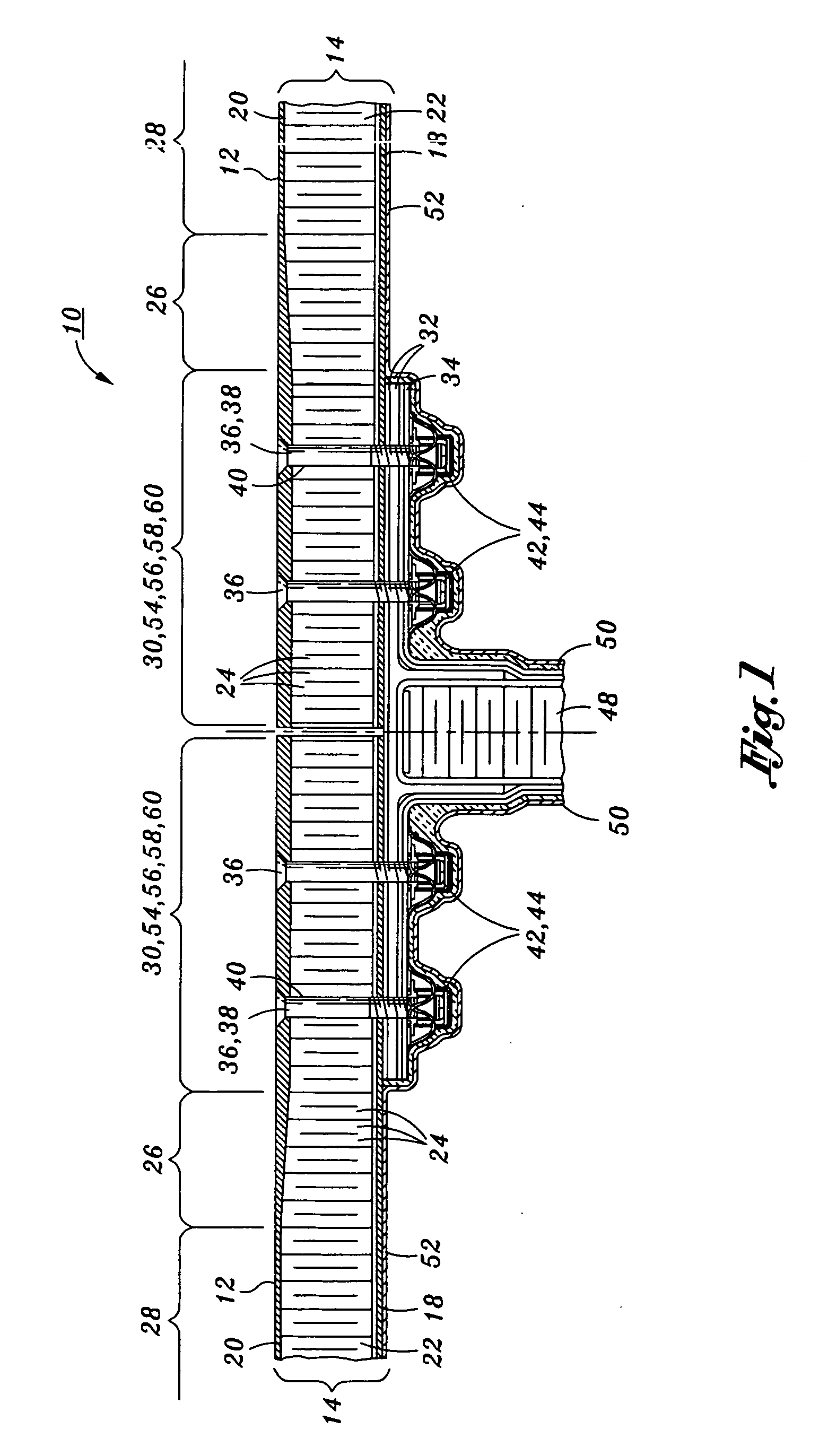
[0024] Referring now to the drawings wherein the showings are for purposes of illustrating the present invention and not for purposes of limiting the same, provided is a composite joint 10 that is uniquely configured for minimizing heat conduction through mechanical fasteners 36 which interconnect the composite panels 12. The composite joint 10 is specifically configured to prevent heat transfer across the composite joint 10.

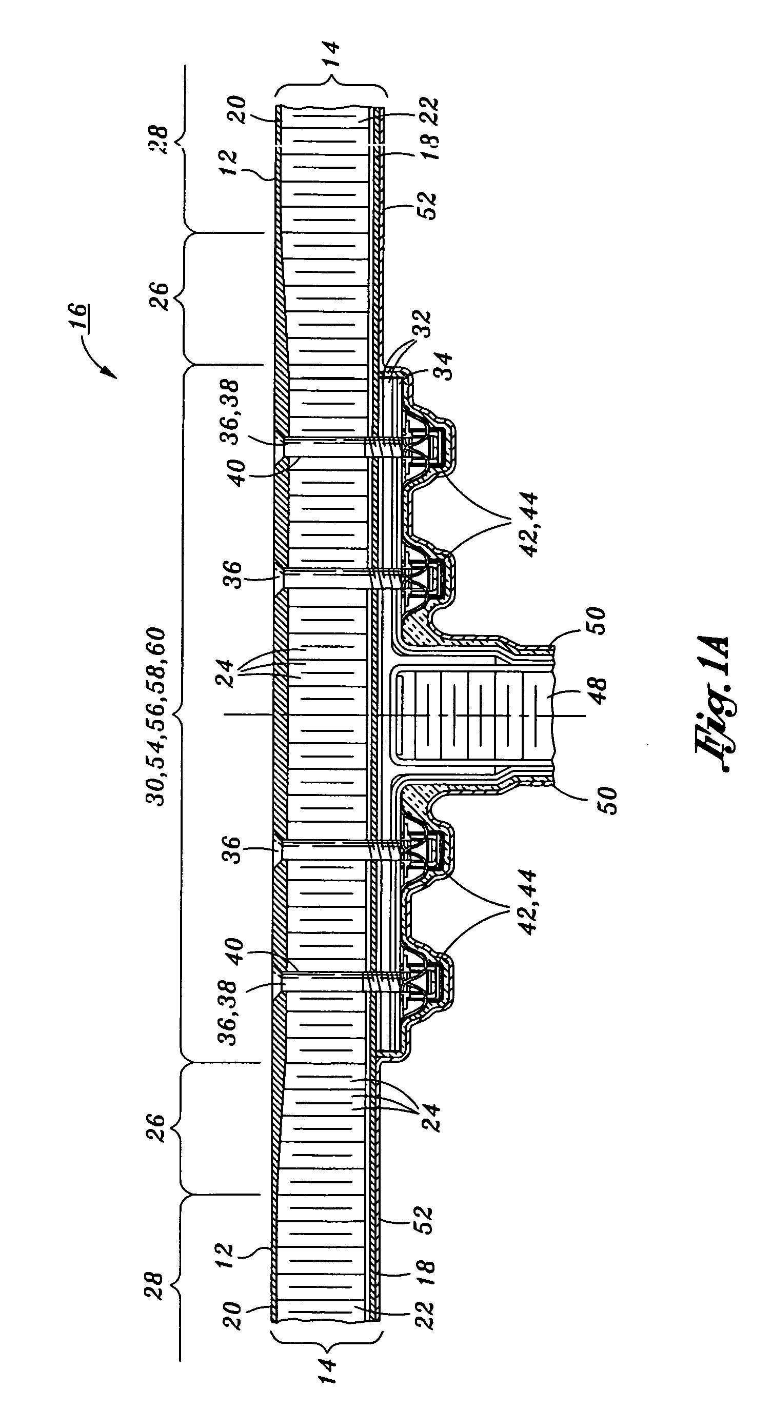
[0025] It should be noted that the present invention may be configured as a composite joint as shown in FIG. 1 or as a composite structure as shown in FIG. 1a. The composite joint shown in FIG. 1 comprises a pair of adjoining composite panels and a primary splice plate. In its broadest sense, the composite joint 10 comprises the pair of adjoining composites panels, a primary splice plate, and at least one mechanical fastener 36 extending through each one of the composite panels 12 with a layer of thermal barrier compound 56 covering the primary splice plate 32

[...


PUM


Abstract

Provided is a composite joint comprising a pair of composite panels each defining a composite panel thickness and having an inner face sheet and an outer face sheet sandwiching a core panel therebetween. The core panel defines a constant thickness portion and a ramp portion along which the core panel tapers to a reduced thickness portion. The outer face sheet is thickened in the area of the reduced thickness portion. The core panel includes a plurality of cells extending between the inner and outer face sheets. The cells within the reduced thickness portions are filled with a filler material. The cells within the ramp portions and constant thickness portions are filled with aerogel. A primary splice plate extends across the reduced thickness portions. Mechanical fasteners extend through the outer face sheet and into the primary and secondary splice plates. A themal barrier compound covers the primary splice plate.

Description

CROSS-REFERENCE TO RELATED APPLICATIONS [0001] Not Applicable STATEMENT RE: FEDERALLY SPONSORED RESEARCH / DEVELOPMENT [0002] Not Applicable BACKGROUND OF THE INVENTION [0003] The present invention relates generally to structural joints in composite structures and, more particularly, to a uniquely configured composite joint that is specifically adapted to minimize transfer of heat across the composite joint such as between an exterior of the composite structure and an interior thereof. The unique arrangement of the composite joint also provides for an effective sealing of the interior of the composite structure such as may be required in a fuel tank of an aircraft. [0004] In many vehicles such as aircraft, the control of heat flow through certain structural areas is of critical importance in the design of the aircraft. More specifically, certain aircraft constructed of composite materials must be adapted to limit the flow of heat from an exterior of the aircraft to an interior thereof...

Claims


Application Information

Patent Timeline
IPC IPC(8): E04C2/00
CPCF16B5/01Y10T428/197Y10T428/24174Y10T428/24157Y10T428/249923
Inventor BARTLEY-CHO, JONATHAN D.YASAKI, CHRISTOPHER M.POUSHA, F. DONALDREYNOLDS, ROSS S.
Owner NORTHROP GRUMMAN SYST CORP
Why Eureka
Try Eureka