
Method and system for determining lean blow out condition for gas turbine combustion cans

a technology of combustion cans and gas turbines, applied in the direction of machines/engines, failure to burn, etc., can solve the problems of reducing co, hc and nox emissions, affecting the efficiency of combustion, and unable to meet the requirements of combustion,

Inactive Publication Date: 2006-11-09
GENERAL ELECTRIC CO
View PDF13 Cites 24 Cited by
  • Summary
  • Abstract
  • Description
  • Claims
  • Application Information

AI Technical Summary

Benefits of technology

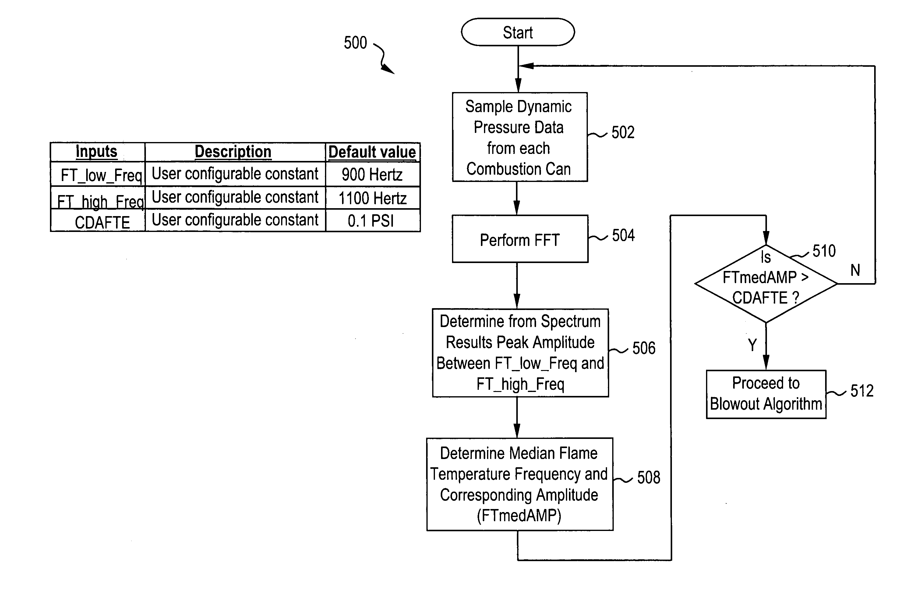
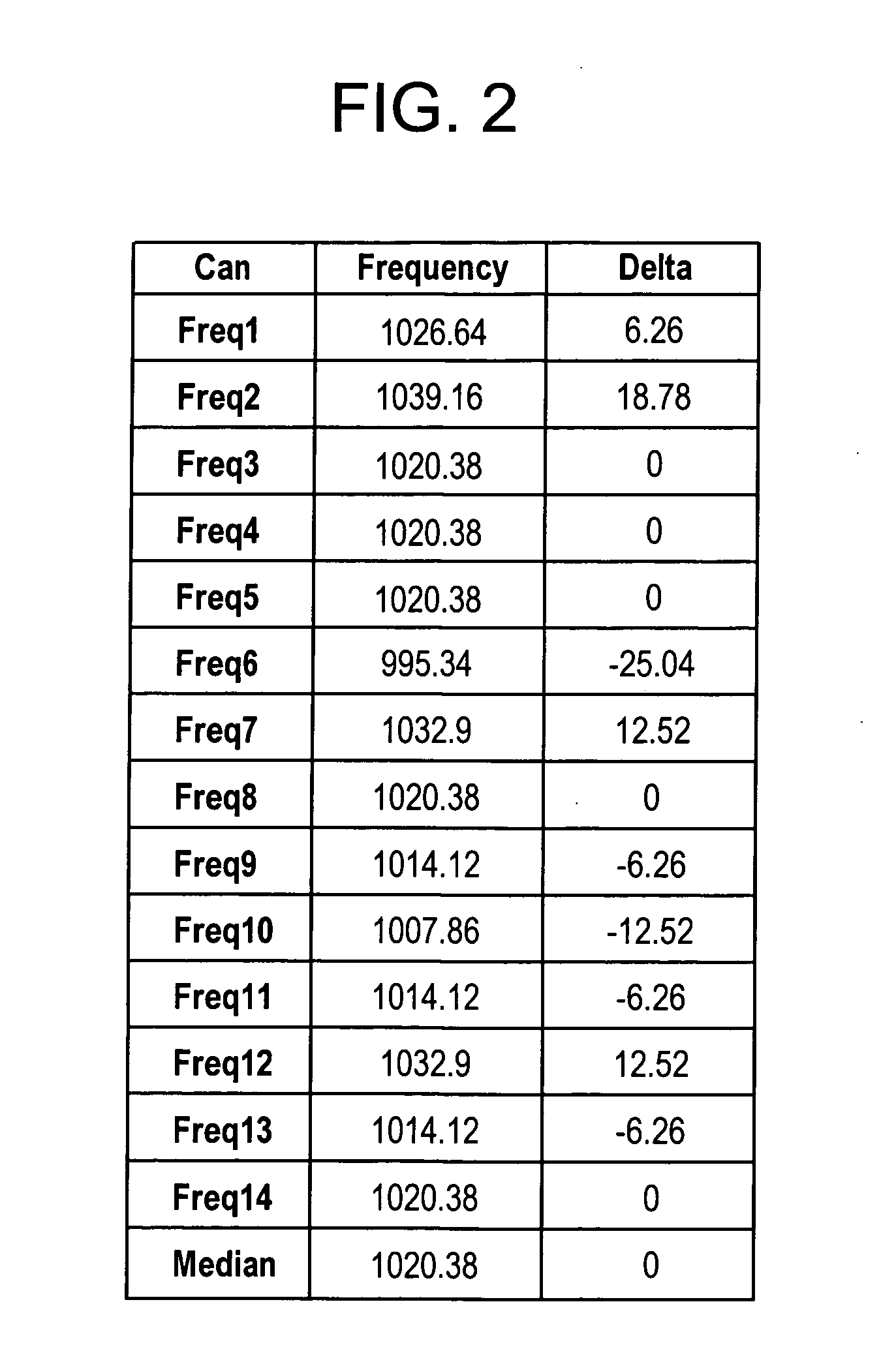
[0010] In another aspect, a method for determining a lean blow out condition for a combustor includes gathering dynamic pressure data for each of a plurality of combustor cans, determining frequency spectral data from the dynamic pressure data, and determining a peak frequency, within an acoustical frequency range, for each of the combustor cans, the peak frequencies indicative of an operating temperature within corresponding combustor cans. A median frequency is determined for the peak frequencies, and the median frequency is subtracted from the peak frequencies for each of the combustor cans. A resulting differential frequency value therebetween is compared to a calculated first blow out alarm level, the first blow out alarm level corresponding to a frequency less than that of the median frequency. A first alarm level indication for a given combustor can is generated whenever the differential frequency value for the given combustor can is less than or equal to the first blow out alarm level.

Problems solved by technology

However, as more air is added to a fixed amount of fuel, the emissions of CO, HC and NOx will decrease until the fraction of air in the fuel-air mixture is large enough that the flame becomes unstable.
Typically, however, lighting a lean pre-mixed fuel-air mixture can be difficult.

Method used


Image

  • Method and system for determining lean blow out condition for gas turbine combustion cans
  • Method and system for determining lean blow out condition for gas turbine combustion cans
  • Method and system for determining lean blow out condition for gas turbine combustion cans

Examples


Embodiment Construction

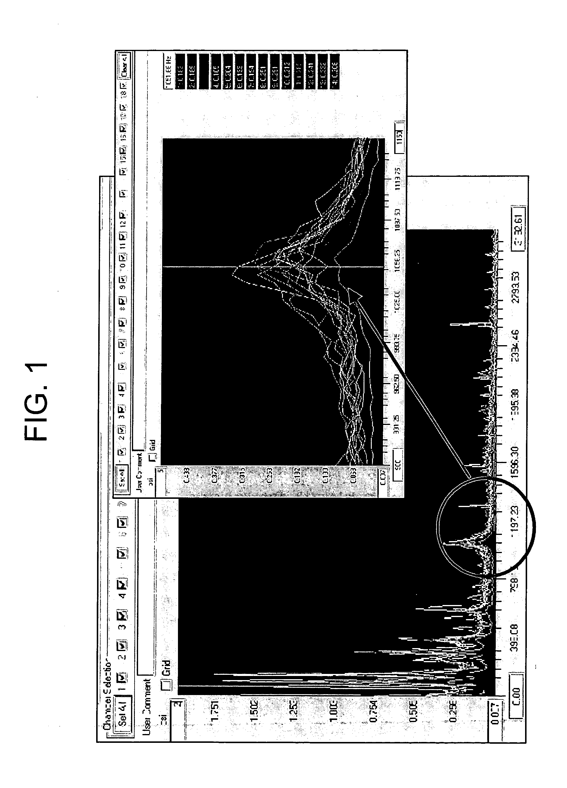
[0022] Disclosed herein is a method and system for predicting when a turbine combustor is approaching a lean blow out condition, and to thereafter generate an alarm to indicate that corrective action is to be taken in order to reduce the risk of flame blowing out in the combustor. Briefly stated, the methodology described herein is based on measuring the frequency of one of the acoustic modes (e.g., a standing wave which is generated at resonance frequencies of combustor) occurring inside the combustion chamber. This acoustic mode travels in a direction that is transverse to the axis of the combustion liner, and the frequency of this mode is determined by the geometric dimensions of the combustor as well as the speed of sound of the gas inside the combustion chamber.

[0023] The speed of sound of the gas may in turn be calculated from the gas temperature and gas properties. Thus, by measuring the resonant frequency and by knowing the combustor dimensions and gas properties, the tempe...


PUM


Abstract

A method for determining a lean blow out condition for a combustor. In an exemplary embodiment, the method includes determining acoustical frequency data for the combustor, determining a combustor flame temperature based on the acoustical frequency data, determining an existing fuel / air ratio in the combustor based on the combustor flame temperature, and comparing the existing fuel / ratio to a lean blow out fuel / air ratio. A lean blow out condition for the combustor is indicated when the existing fuel / air ratio is about equal to the lean blow out fuel / air ratio.

Description

BACKGROUND OF THE INVENTION [0001] The present disclosure relates generally to industrial power plant machinery and, more particularly, to a method and system for determining a lean blow out condition for gas turbine combustion cans. [0002] Gas turbines generally include a compressor and turbine arranged on a rotating shaft(s), and a combustion section between the compressor and turbine. The combustion section burns a mixture of compressed air and liquid and / or gaseous fuel to generate a high-energy combustion gas stream that drives the rotating turbine. The turbine rotationally drives the compressor and provides output power. Industrial gas turbines are often used to provide output power to drive an electrical generator or motor. Other types of gas turbines may be used as aircraft engines, on-site and supplemental power generators, and for other applications. Certain gas turbines include several tangentially located combustor cans that burn fuel in high-pressure compressed air to i...

Claims


Application Information

Patent Timeline
Patent Type & Authority Applications(United States)
IPC IPC(8): F02C7/00
CPCF01D21/003F02C9/00F23N5/242F05D2270/301F23N2031/06F05D2270/092F05D2270/14F23N2025/04F23N2231/06F23N2225/04
Inventor MICK, WARREN JAMESWILLIAMS, GEORGE EDWARDHAN, FEIGLEESON, EAMON PATRICKSRINIVASAN, SHIVAKOPCHO, SCOTT ALANLEIBU, ILAN
Owner GENERAL ELECTRIC CO
Learn More