Plate for heat exchanger

a heat exchanger and plate technology, applied in the direction of heat exchanger fins, lighting and heating apparatus, stationary conduit assemblies, etc., can solve the problems of affecting the cooling performance of the air conditioner, so as to improve the flow distribution of refrigerant, prevent overcooling/overheating, and reduce the pressure drop of refrigeran

Inactive Publication Date: 2006-11-09
HANON SYST
View PDF15 Cites 17 Cited by
  • Summary
  • Abstract
  • Description
  • Claims
  • Application Information

AI Technical Summary

Benefits of technology

[0018] The present invention has been made to solve the foregoing problems and it is therefore an object of the present invention to provide a heat exchange which has streamline first beads for imparting turbulence to refrigerant flowing through channels of plates and second beads in refrigerant distributing sections for forming guide beads extended to first rows of the first beads in order to decrease the pressure drop of refrigerant and improve the flow distribution of refrigerant into uniform state, thereby preventing overcooling / overheating as well as stabilizing an air conditioning system and improving the cooling performance thereof.

Problems solved by technology

In the overcooled section, a problem of icing may occur in the surface of the evaporator.
In the overheated section, the temperature variation of air degrades the performance of the air conditioning system thereby causing unstableness to the air conditioning system.
This also increases the temperature distribution variation of the air passing through the evaporator thereby to degrade the cooling performance.

Method used


Image

  • Plate for heat exchanger
  • Plate for heat exchanger
  • Plate for heat exchanger

Examples


first embodiment

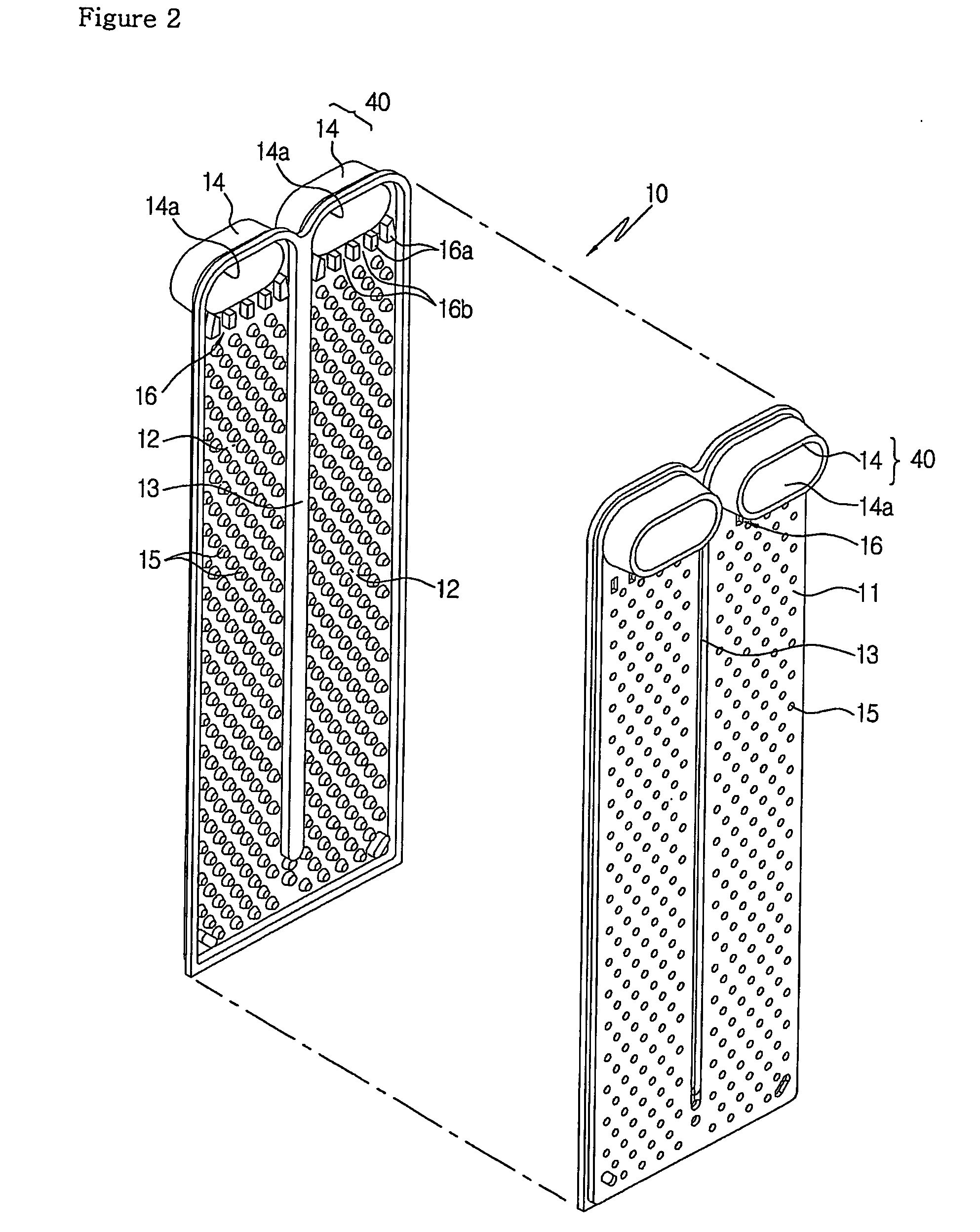
[0081] Instead of being circularly shaped, the first beads 115a may be formed streamlined as in the first embodiment, which will be described again later in the specification.

[0082] Further, the first beads 115a have the spacing S between longitudinally adjacent beads 115a in the range of 0.3 to 5.0 mm.

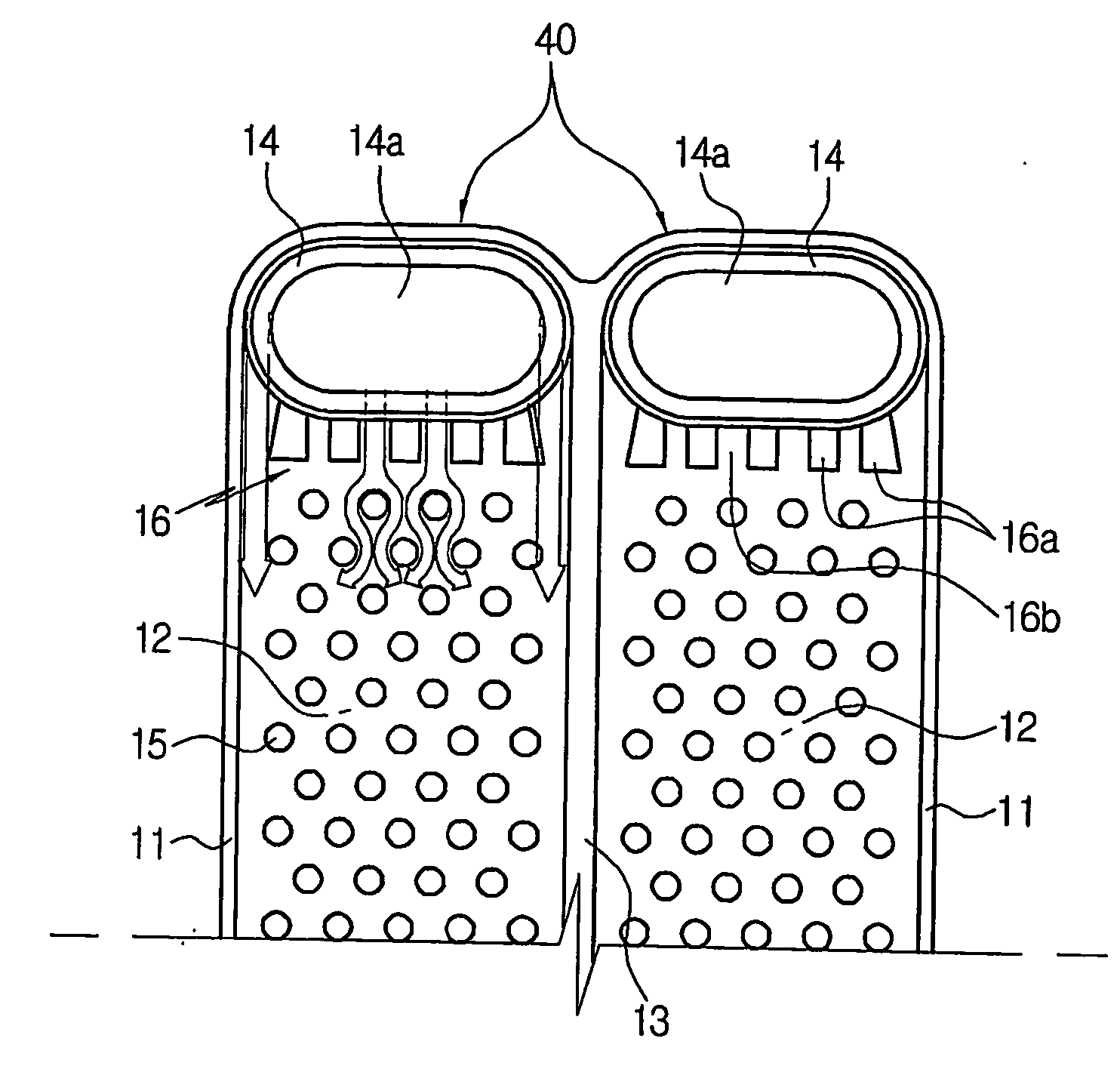
[0083]FIG. 14 compares the flow distribution of refrigerant by a conventional refrigerant distributing section with that of the refrigerant distributing section having the guide beads. As seen in FIG. 14, although it is required that refrigerant introduced from a tank 118 should be uniformly distributed toward the channel 112 after flowing through the refrigerant distributing section 116, the conventional refrigerant distributing section 116 (of the prior art) fails to uniformly distribute refrigerant so that refrigerant is crowded in the periphery.

[0084] On the contrary, it is observed in the refrigerant distributing section 116 having the guide beads 117 that refrigerant flowing t...

third embodiment

[0088] As shown in FIGS. 16 to 20, the third embodiment has streamline first beads 115 and guide beads 117a among second beads 116a of refrigerant distributing sections 116.

[0089] That is, this embodiment embraces all effects obtainable from the streamline first beads 115 of the first embodiment and from the guide beads 117 formed in the second beads 116a of the refrigerant distributing sections 116 of the second embodiment in order to achieve the maximum performance.

[0090] Preferably, the width W to length L ratio W / L of a first bead 115 satisfies a suitable range defined by an equation of 0.35≦W / L≦0.75 as in the above embodiment, and the spacing S between longitudinally adjacent beads 115 satisfies an equation 0.3 mm≦S≦5.0 mm.

[0091] Also, a guide bead 117a in the center of second beads 116a formed in the refrigerant distributing section 116 is extended to a first row of the first beads 115.

[0092] Preferably, one of the first beads 115 in the first row corresponding to the guide...


PUM


Abstract

The present invention relates to a heat exchanger plate, more particularly, in which a number of beads for imparting turbulence to refrigerant flowing through a channel of a plate are formed streamlined and guide beads arre formed in refrigerant distributing sections in order to reduce the pressure drop of refrigerant while realizing uniform refrigerant distribution. In the heat exchanger plate of a tube including a tank communicating with a channel, a number of first beads so arrayed in the plate that opposed sides are coupled to each other to impart turbulence to refrigerant flowing through the channel and refrigerant distributing sections provided in inlet and outlet sides of the channel and divided by at least one second bead to have a plurality of paths, the first beads are formed streamlined and satisfy an equation of 0.35≦W/L≦0.75, wherein W is the width and L is the length.

Description

TECHNICAL FIELD [0001] The present invention relates to a heat exchanger plate, more particularly, in which a number of beads for imparting turbulence to refrigerant flowing through a channel of a plate are formed streamlined and guide beads are formed in refrigerant distributing sections in order to reduce the amount of the pressure drop of refrigerant while realizing uniform refrigerant distribution. BACKGROUND ART [0002] In general, a heat exchanger refers to a device in which an interior refrigerant passage is formed so that refrigerant exchanges heat with external air while being circulated through the refrigerant passage. The heat exchanger is used in various air conditioning devices, and is employed in various forms such as a fin tube type, a serpentine type, a drawn cup type and a parallel flow type according to various conditions in which it is used. [0003] The heat exchanger has an evaporator-using refrigerant as heat exchange medium, which is divided into one-, two- and f...

Claims


Application Information

Patent Timeline
Patent Type & Authority Applications(United States)
IPC IPC(8): F28D1/03F28F13/12F28F3/04
CPCF28D1/0341F28F9/0282F28F3/044F28D2021/0071F28F2215/04F28F2250/02F28F13/12
Inventor PARK, TAEYOUNGOH, KWANGHEONJUN, GILWOONGLEE, JUNGJAE
Owner HANON SYST
Why Eureka
Try Eureka