
Electrical cable having a surface with reduced coefficient of friction

a technology of electric cables and coefficients, which is applied in the direction of cables, insulated conductors, coatings, etc., can solve the problems of large alteration of manufacturing lines, high coefficients of external friction, and inability to control the thickness of the sheath properly

Inactive Publication Date: 2006-11-09
SOUTHWIRE CO LLC
View PDF24 Cites 35 Cited by
  • Summary
  • Abstract
  • Description
  • Claims
  • Application Information

AI Technical Summary

Benefits of technology

The present invention provides a method for making a cable with a surface that has reduced coefficient of friction, which makes it easier to install the cable. The method involves mixing a lubricating material with the sheath material of the cable. The lubricating material can be heated or not, and the sheath material can be heated or not. The sheath material can be introduced in pellet form to an extruder and then optionally cooled. The lubricating material can be selected from fatty amides, hydrocarbon oils, and mixtures thereof. The lubricating material can be added at any point in the manufacturing process before the sheath material is formed. The cable also has a low melting or softening temperature, which allows for easier installation. The lubricating material can be added to the outermost sheath material or to the inner most sheath material. The cable has a sheath coating that incorporates the lubricating material, which helps to reduce friction during installation.

Problems solved by technology

Such cables present the disadvantage that their exterior surface has a high coefficient of friction, so that they are awkward to fit in internal sections of walls and ceilings or conduits, since when they come into contact with the surfaces they become stuck or difficult to pull, etc.
That gives rise to a major alteration of the manufacturing line.
In addition, the equipment for depositing the lubricant must be very close to the sheath extrusion head since otherwise it is not possible to control the thickness of the sheath properly.
In any event, the additional equipment occupies non-negligible space and such an arrangement is not favorable for control over the dimensions of the sheath.
Whatever the prior art method used, the manufacture and / or installation of said cables involves a considerable loss of time and an economic cost, since alternative materials are required.

Method used


Image

  • Electrical cable having a surface with reduced coefficient of friction
  • Electrical cable having a surface with reduced coefficient of friction
  • Electrical cable having a surface with reduced coefficient of friction

Examples


example

[0049] To understand the affects of the jacket lubricant system on the ease of pull variations of the UL (Underwriters Laboratories, Inc.) joist pull test was utilized.

[0050] The joist pull test outlined in UL 719 Section 23 establishes the integrity of the outer PVC jacket of Type NM-B constructions when subjected to pulling through angled holes drilled through wood blocks.

[0051] The test apparatus consists of an arrangement of 2″×4″ wood blocks having holes drilled at 15° drilled through the broad face. Four of these blocks are then secured into an frame so that the centerlines of the holes are offset 10″ to create tension in the specimen through the blocks. A coil of NM-B is placed into a cold-box and is conditioned at −20° C. for 24 hours. A section of the cable is fed through corresponding holes in the blocks where the end protruding out of the last block is pulled through at 45° to the horizontal. The cable is then cut off and two other specimens are pulled through from the ...


PUM

PropertyMeasurementUnit
temperatureaaaaaaaaaa
temperaturesaaaaaaaaaa

Abstract

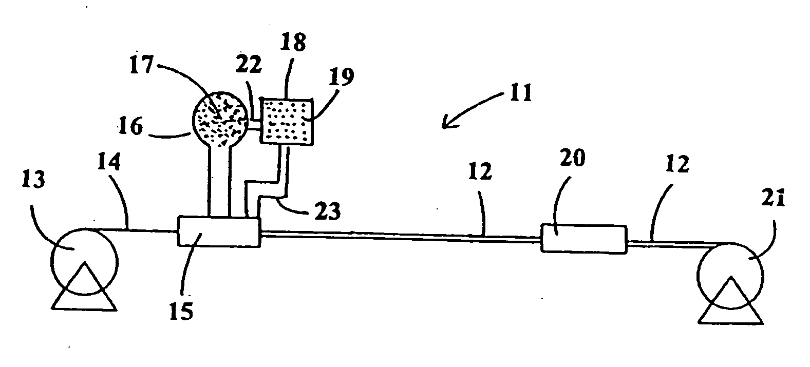
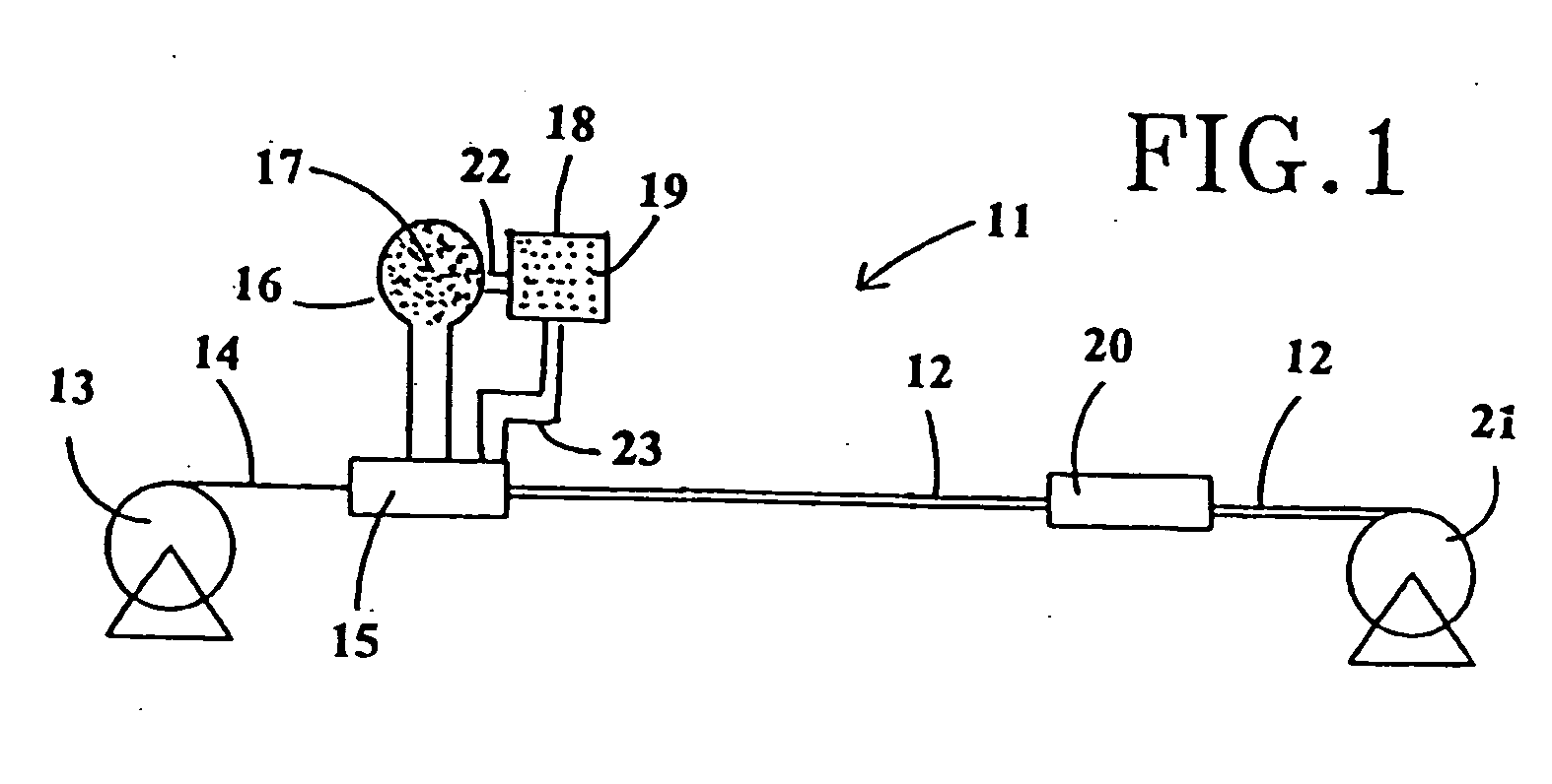
The present invention includes a cable having reduced surface friction and the method of manufacture thereof including steps in which a conductor wire is coated with a first plastic material and with a mixture of a second plastic material and lubricating material and the coated conductor wire cooled. The cable includes at least one conductor core and at least two coatings of plastic material and incorporates a lubricating material in and / or on the outer layer of plastic material. The equipment for the manufacturing of the electrical cable includes a reel for supplying a conductor wire to an extruding head, which is connected to tanks containing plastic material and lubricating material for coating the conducting wire, and a reel for taking up the cable.

Description

[0001] This application is a continuation-in-part of U.S. patent application Ser. No. 11 / 120,487, filed May 3, 2005 which claims the benefit of priority of U.S. Provisional Patent Application No. 60 / 587,584 filed Jul. 13, 2004, and U.S. patent application Ser. No. 10 / 952,294, filed Sep. 28, 2004 which are herein incorporated by reference.[0002] The present invention relates to an electrical cable and to a method of and equipment for reducing its coefficient of friction. BACKGROUND OF THE INVENTION [0003] Electrical cables which include at least one conductor core and at least one coating are well known. [0004] Such cables present the disadvantage that their exterior surface has a high coefficient of friction, so that they are awkward to fit in internal sections of walls and ceilings or conduits, since when they come into contact with the surfaces they become stuck or difficult to pull, etc. [0005] In order to overcome said difficulty, alternative materials such as vaselines and the ...

Claims


Application Information

Patent Timeline
Patent Type & Authority Applications(United States)
IPC IPC(8): H01B7/00
CPCB05D5/08B05D7/14B05D7/52H01B13/145H01B7/1885H01B13/141B05D2256/00
Inventor KUMMER, RANDY D.REECE, DAVIDDIXON, MARK D.CARLSON, JOHN R.LAM, HAISASSE, PHILIP
Owner SOUTHWIRE CO LLC
Learn More