Ultrasonic motor driving device and ultrasonic diagnosis apparatus

a driving device and ultrasonic technology, applied in piezoelectric/electrostrictive device details, instruments, therapy, etc., can solve the problems of unstable operation, life shortened, and inability to obtain three-dimensional images, so as to prevent unstable operation of ultrasonic motors

Inactive Publication Date: 2006-11-09
KONICA MINOLTA INC
View PDF5 Cites 126 Cited by
  • Summary
  • Abstract
  • Description
  • Claims
  • Application Information

AI Technical Summary

Benefits of technology

[0024] According to the present invention, unstable operation of the ultrasonic motor can be prevented when the ultrasonic motor is driven at the lower speed out of at least two types of speeds and life extension can be attempted.
[0025] In addition, according to other embodiments of the present invention, unstable operation of the ultrasonic motor can be prevented without affecting the diagnostic operations by the user and life extension can be attempted.

Problems solved by technology

However, if the ultrasonic motor is driven for a long period of time at a comparatively low speed, problems occur in that, roughness occurs on the pectinate surface of stator 52, on the side in contact with rotor 53, and in addition, a stable operation can no longer be attained because the fine particles of this stator 52 are transferred to the contact surface of the rotor 53, and life is shortened.
Furthermore, in an ultrasonic diagnostic device utilizing this ultrasonic motor, a three-dimensional image cannot be obtained because stable operation can no longer be attained.

Method used


Image

  • Ultrasonic motor driving device and ultrasonic diagnosis apparatus
  • Ultrasonic motor driving device and ultrasonic diagnosis apparatus
  • Ultrasonic motor driving device and ultrasonic diagnosis apparatus

Examples


first embodiment

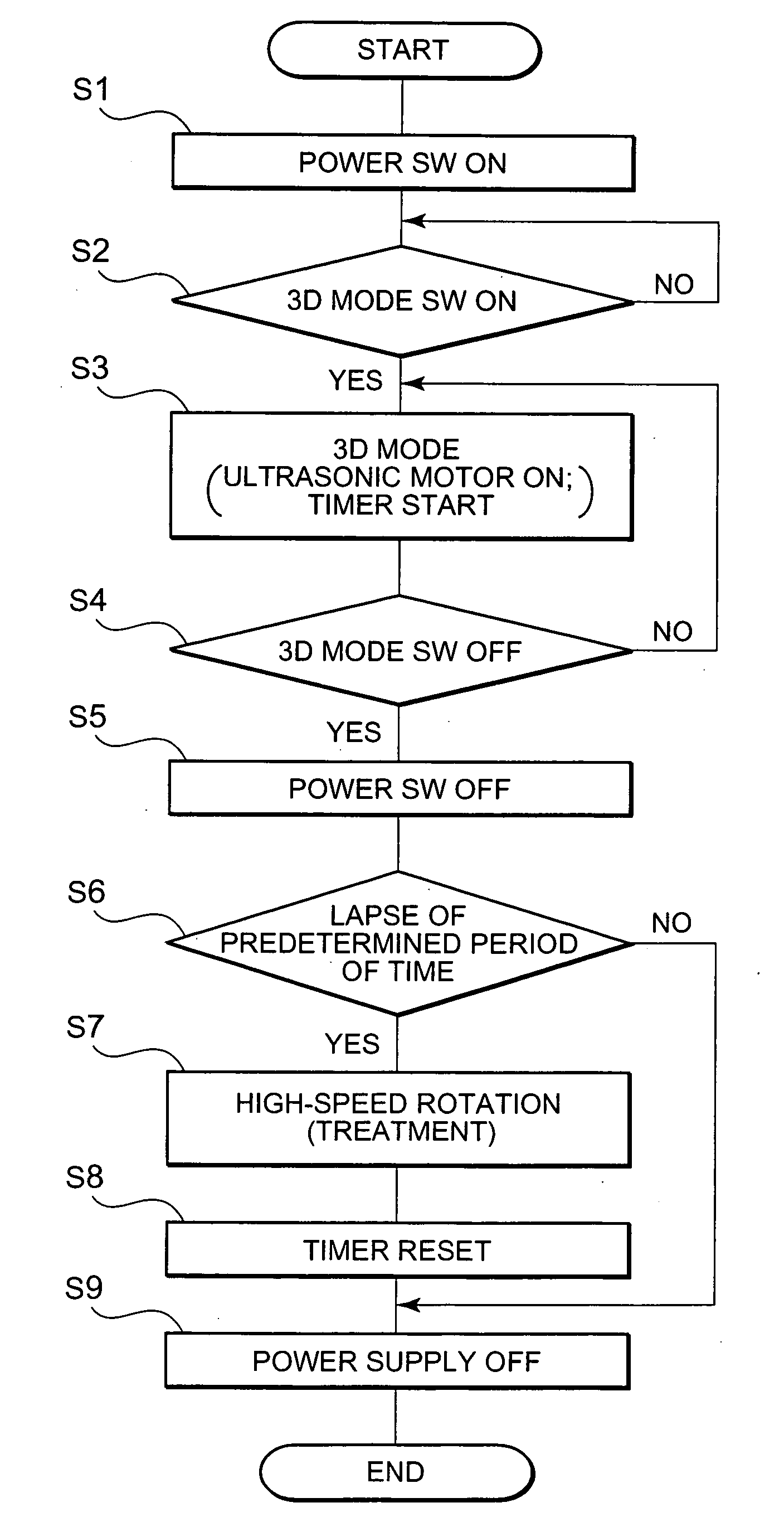
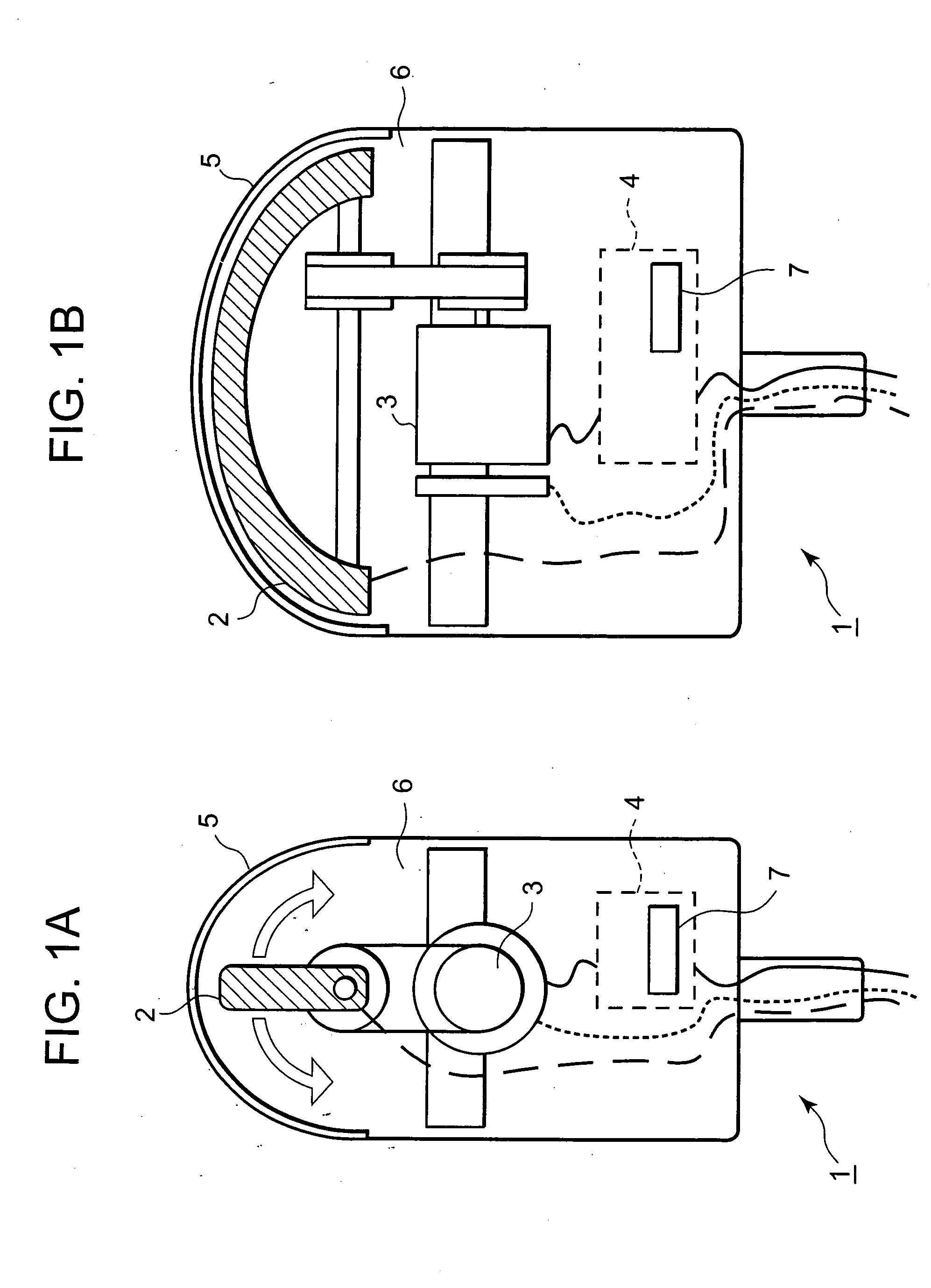
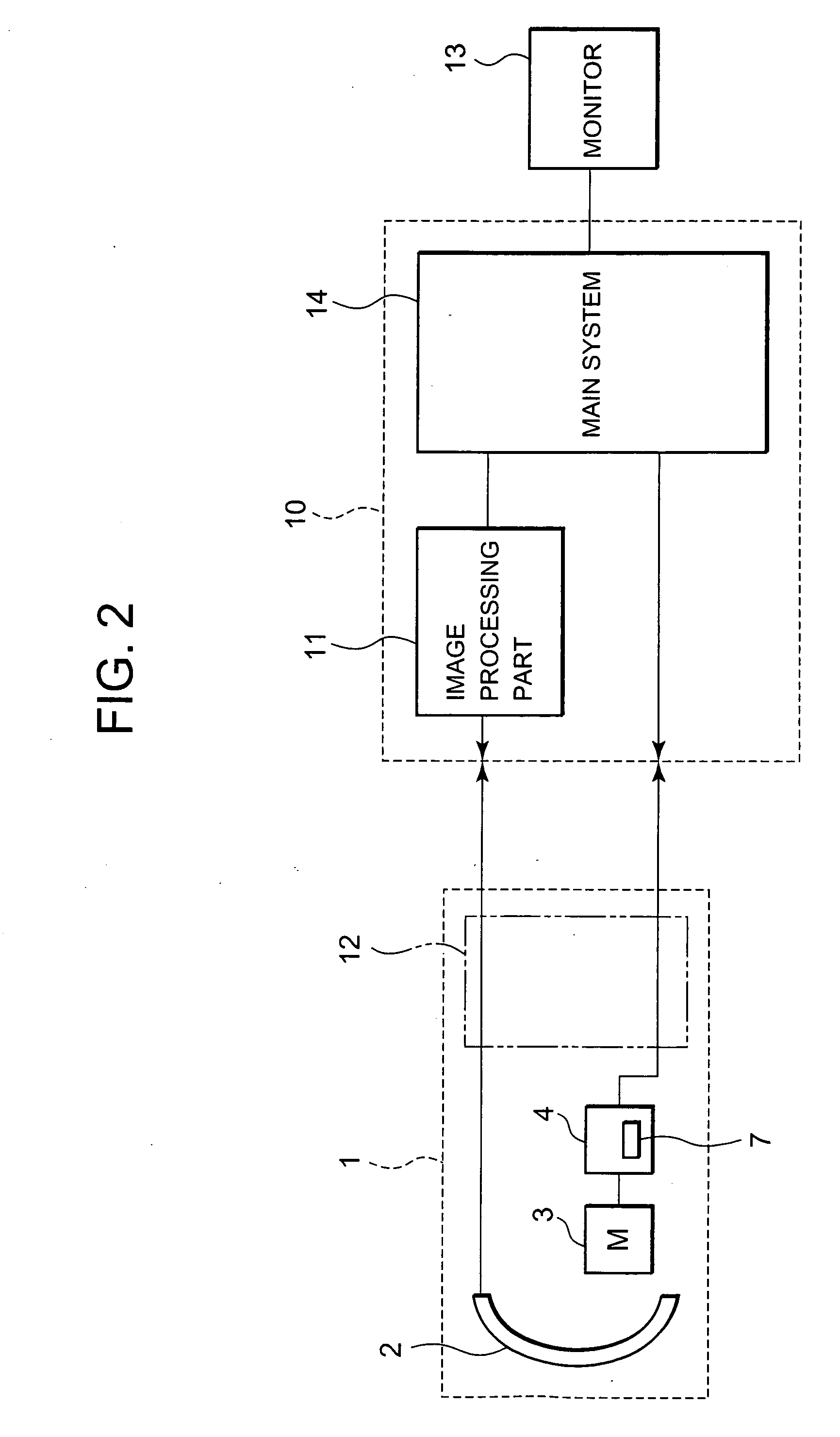
[0038]FIG. 3 is a flowchart showing an embodiment applied to the ultrasonic diagnostic device shown in FIG. 1A, FIG. 1B, and FIG. 2, as one example, and the operation of a main system 14 of the ultrasonic diagnostic device main unit 10. Incidentally, if the device-side performs a treatment on its own while the user is performing an ultrasonic diagnosis, this interferes with the diagnosis. Therefore, in a first embodiment, under the premise that the user is not performing a diagnosis, the speed control means 7 switches and controls the speed from low-speed to high-speed when the user has turned the power SW off, and the treatment is performed.

[0039] In FIG. 3, first, the power SW (unillustrated) of the ultrasonic diagnostic device main unit 10 is turned ON (step S1), a state enabling ultrasonic diagnosis is entered; furthermore, when 3D mode SW (unillustrated) is turned ON (Y in step S2), ultrasonic diagnosis in 3D mode begins, ultrasonic motor 3 is ON, and the timer starts (step S3...

second embodiment

[0041] Next, a second embodiment is described with reference to FIG. 4. In the second embodiment, under the premise that the user is not performing a diagnosis, treatment is performed when the screensaver function of monitor 13 is in operation. In FIG. 4, first, the power SW (unillustrated) of the ultrasonic diagnostic device main unit 10 is turned ON (step S1); furthermore, when 3D mode SW (unillustrated) is turned ON (Y in step S2), ultrasonic diagnosis in 3D mode begins, ultrasonic motor 3 is ON, and the timer starts (step S3). Next, whether or not the screensaver has been turned ON is determined (step S4a), and if it is not ON, ultrasonic diagnosis in 3D mode is continued (step S4a→S3); on the other hand, if the screensaver is turned ON, it is determined whether or not the predetermined period of time elapsed on the timer (step S4a→S6). Then, if the predetermined period of time has elapsed, treatment is performed (step S7), the timer is reset (step 8), and subsequently, the proc...

third embodiment

[0043] Next, a third embodiment is described with reference to FIG. 5. In the third embodiment, treatment is performed immediately after the user has turned the power SW ON for the first time within one day. In FIG. 5, first, when the power SW (unillustrated) of the ultrasonic diagnostic device main unit 10 is turned ON (Y in step 11), it is determined whether or not the previous power SW OFF was today, or in other words, whether or not it was yesterday or before (step S12). Then, if the previous power SW OFF was yesterday or before, it is determined whether or not treatment was previously performed (step S12→S13), and if it was not performed, treatment is performed (step S13→S14). The determination step of step S13 can be omitted, and treatment can be performed unconditionally when the user has turned the power SW ON for the first time within one day.

[0044] Through the foregoing construction, unstable operation of the ultrasonic motor can be prevented without affecting the diagnos...


PUM


Abstract

A technology, wherein unstable operation of the ultrasonic motor is prevented, when the ultrasonic motor is driven at the lower speed out of at least two types of speeds, and life extension is attempted, is disclosed, and according to this invention, when the ultrasonic motor 3 is driven at a comparatively low-speed during normal driving, unstable operation due to driving at a comparatively low-speed can be prevented and life extension can be attempted by driving the ultrasonic motor at a comparatively high-speed every predetermined period of time.

Description

TECHNICAL FIELD [0001] The present invention relates to an ultrasonic motor driving device for driving an ultrasonic motor. [0002] The present invention also relates to an ultrasonic diagnostic device for obtaining three-dimensional images by scanning sonic elements by driving an ultrasonic motor. BACKGROUND ART [0003] An ultrasonic motor generally has a construction such as that described in Patent Reference 1, below. Hereafter, this construction is explained, with reference to the rough cross-sectional diagram shown in FIG. 7. In this example, stator 52 and rotor 53 are constructed such as to be pressurized by spring 54 and appressed. The surface of stator 52 which is in contact with rotor 53 is formed as a pectinate, and piezoelectric ceramic 51 is provided on the surface on the opposite side thereof. In a construction as such, traveling wave is generated in piezoelectric ceramic 51 when ultrasonic wave is impressed thereto, and this traveling wave is transmitted to rotor 53 via ...

Claims


Application Information

Patent Timeline
Patent Type & Authority Applications(United States)
IPC IPC(8): H01L41/09A61B8/00A61N7/02G01S15/89G10K11/35H01L41/04H02N2/14
CPCA61B8/00A61B8/12A61B8/4461A61B8/4483A61B8/445A61N7/022G01S15/894G10K11/355H02N2/14A61B8/483
Inventor KOIZUMI, JUNIRIOKA, KAZUYOSHIONOZUKA, MASAO
Owner KONICA MINOLTA INC
Why Eureka
Try Eureka