Power Factor Correction Analysis System and Method

a power factor and analysis system technology, applied in the field of system and method for correcting power factor, can solve the problems of large reactive power and often large inductance of the power system of electric motors, and achieve the effect of reducing reactive power, reducing reactive power, and reducing reactive power

a power factor and analysis system technology, applied in the field of system and method for correcting power factor, can solve the problems of large reactive power and often large inductance of the power system of electric motors, and achieve the effect of reducing reactive power, reducing reactive power, and reducing reactive power

US20060250117A1Inactive Publication Date: 2006-11-09TITON ENERGY

Image

  • Power Factor Correction Analysis System and Method
  • Power Factor Correction Analysis System and Method
  • Power Factor Correction Analysis System and Method

Examples


Embodiment Construction

)

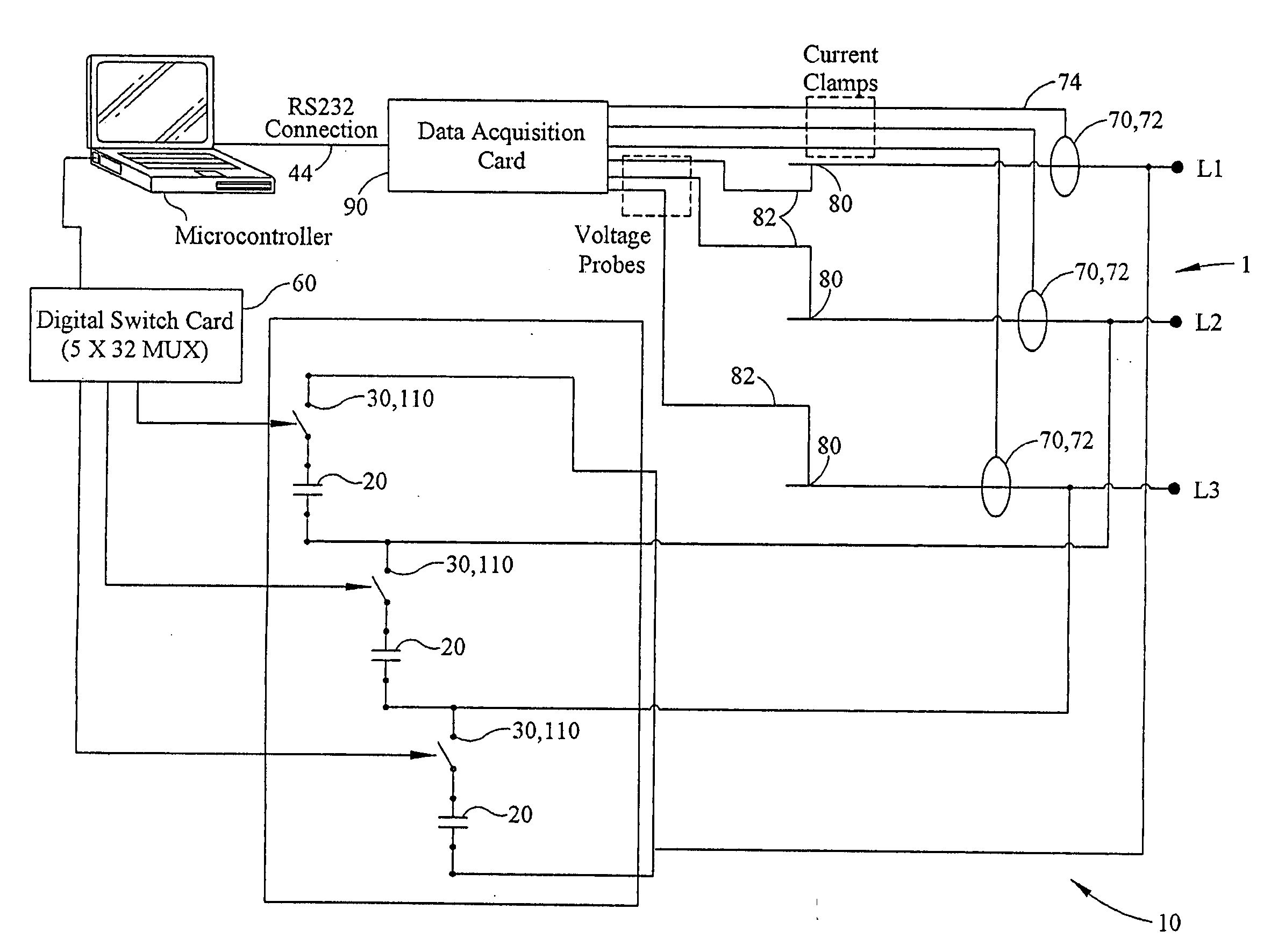
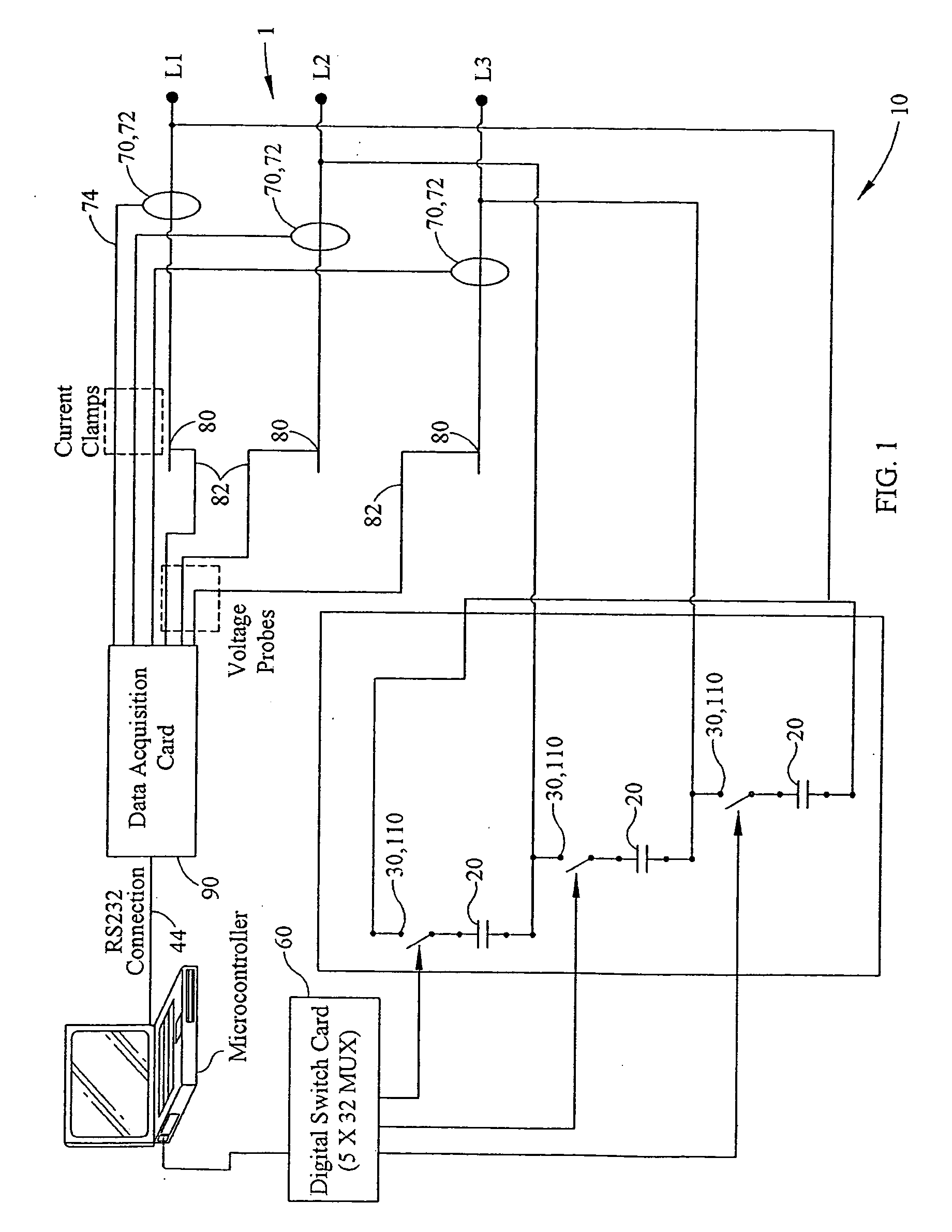
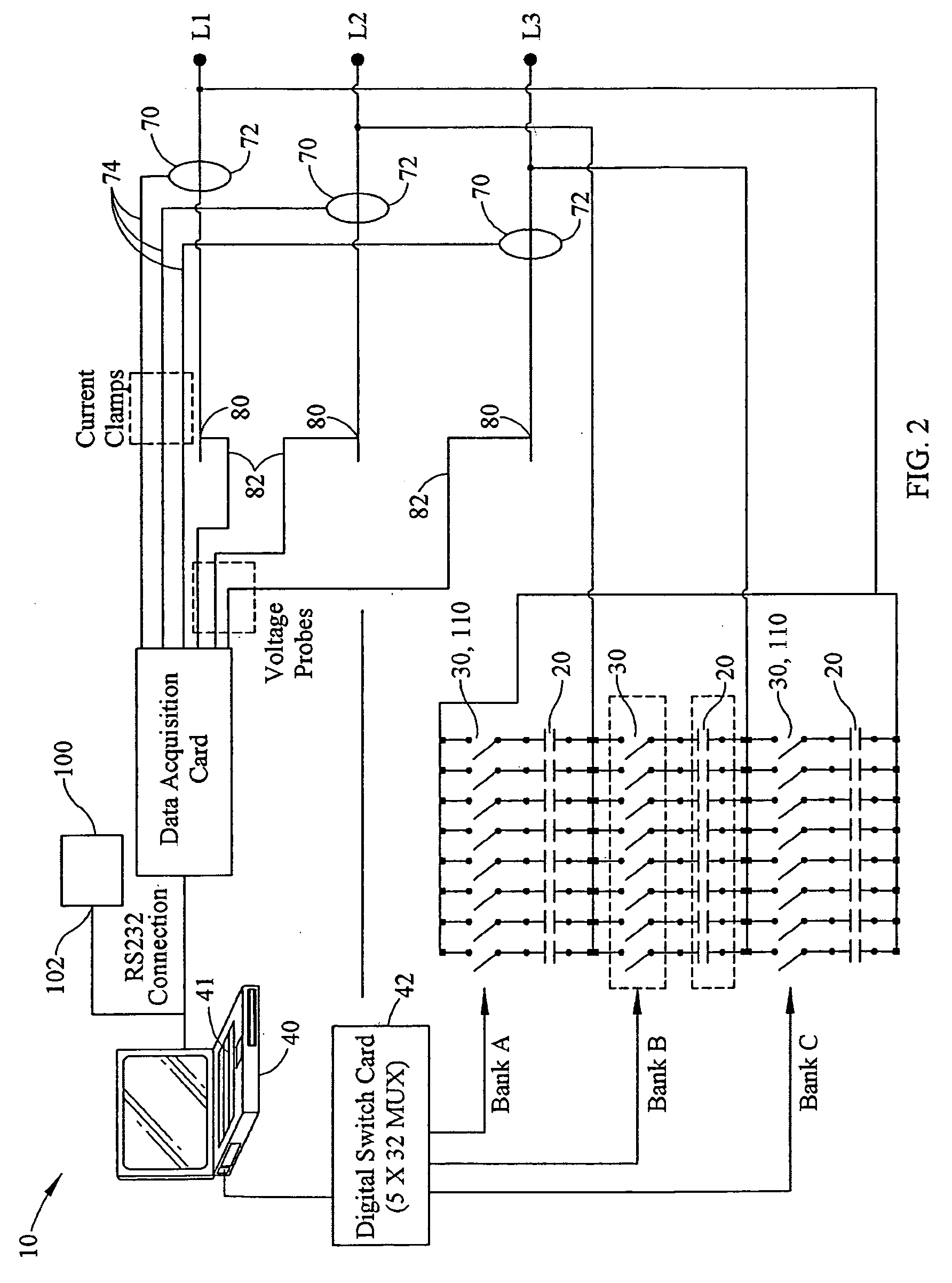
[0016] Referring now to the drawing Figures, and in accordance with a preferred constructed embodiment of the present invention, an apparatus 10 for determining the necessary capacitance for correcting power factor in an electrical power distribution system comprises a plurality of conventional capacitors 20 electrically connected in series with a plurality of switches 30 both disposed between a line-line voltage in, for example, a three-phase power system 1. For purposes of the present disclosure, a three phase line-line power system will be described and shown in the drawing Figures. However, one of ordinary skill in the art will recognize that the instant invention is capable of being practiced in conjunction with a plurality of one, two and three phase power systems without departing from the teachings herein.

[0017] As best seen in FIG. 1, a basic three phase circuit design comprises a single capacitor 20 in series with a switch 30, placed in parallel with a line-line voltage....


PUM


Abstract

An apparatus for determining the necessary capacitance required to correct power factor in an electrical power system comprises a plurality of capacitors having predetermined capacitances connected in series with a plurality of switching devices, said capacitances and switching devices connected between the line voltages of said power system to correct power factor. A means for determining power factor in said power system may include a power factor meter or a plurality of current transmitters and voltage probes used to provide data to a microcontroller to calculate power factor.

Description

CROSS REFERENCE TO RELATED APPLICATIONS [0001] This application claims the benefit of and priority to U.S. Provisional Patent Application Ser. No. 60,678,352 filed May 6, 2005 and entitled “Power Factor Correction Apparatus”.BACKGROUND OF THE INVENTION Field of the Invention [0002] The present invention relates generally to a system and method for correcting power factor in an electrical power distribution system and more specifically to an apparatus that is capable of calculating the appropriate capacitance required for power factor correction and thereby reducing attendant line losses in a power system from the point of installation of the device back to the power source, for example a pole transformer or the like in a residential application. The present invention further includes a system for supplying customers with power factor correction devices employing the requisite capacitance required to correct power factor to a value that is within a predetermined range of unity. SUMMA...

Claims


Application Information

Patent Timeline
09 Nov 2006
Publication
US20060250117A1
IPC
G05F1/70; G05F3/00
CPC
G05F1/70; Y02E40/30; H02J3/1835
Inventors
RAYBURN, DAVID F.