

Method and arrangement for loop test of a disturbed line
- Summary
- Abstract
- Description
- Claims
- Application Information
AI Technical Summary
Benefits of technology
Problems solved by technology
Method used
Image

Examples
Embodiment Construction
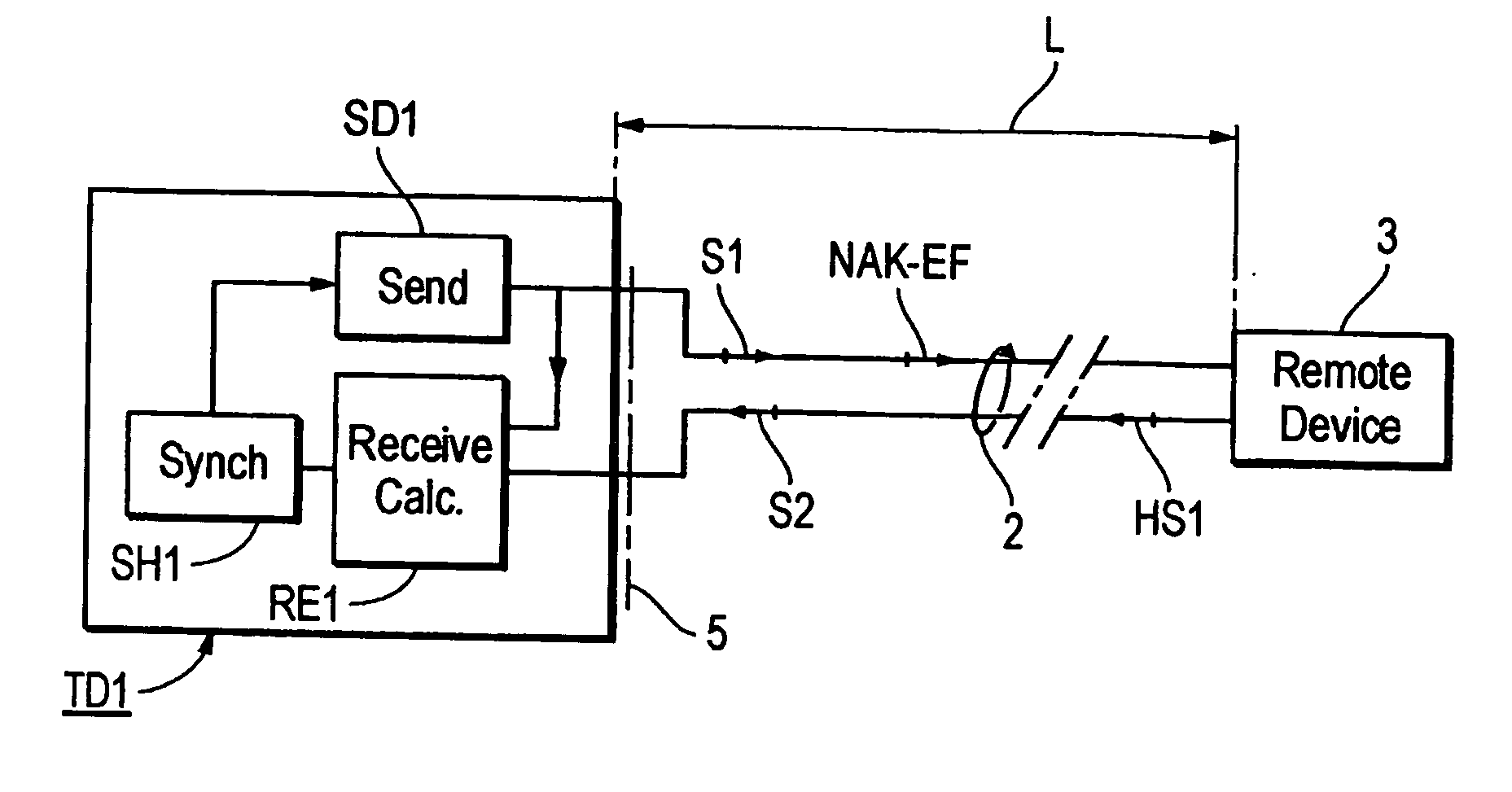
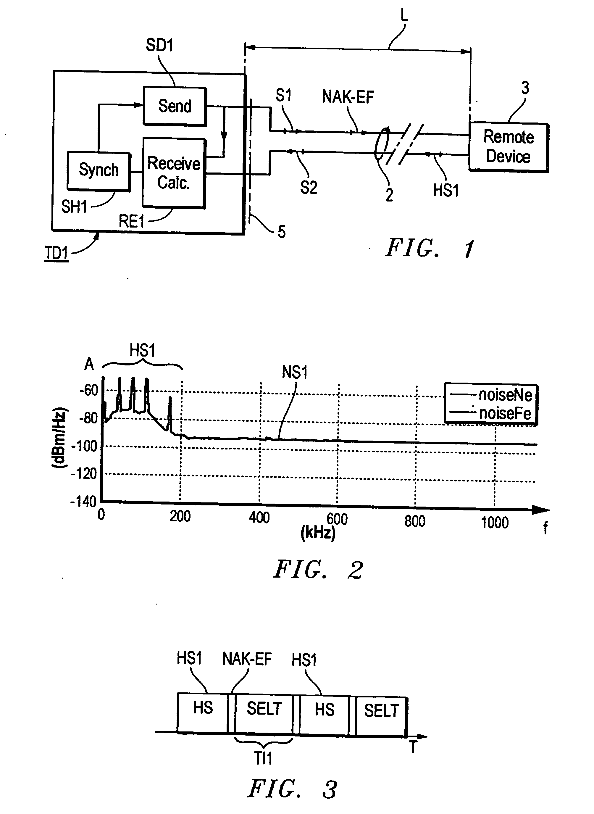
[0030]FIG. 1 shows a simple block schematic over a test device TD1 at a central office, connected to a remote device 3 at a customer's premises via a digital subscriber line 2 (DSL). The line is seen from the end of the test device, and this end is called the near end of the line while the other end at the device 3 is denoted as the remote end. The line 2 is a conventional copper line of a length L, which has certain properties, such as signal attenuation in different frequency ranges. The test device has a sending device SD1, a receiving device RE1 and a synchronizing device SH1. The latter is connected to the sending device SD1, which in turn is connected to the line 2 and to the receiving device RE1.
[0031] As mentioned above it is essential for a network operator to be able to utilize the already existing copper line 2 for the broadband transmission. The operator therefore must know the line properties, such as the length L, signal attenuation and transmission capacity. These pr...
PUM
 Abstract
Description
Claims
Application Information