
System and method for programming an inactivity timer

a timer and inactivity technology, applied in the direction of network topologies, messaging/mailboxes/announcements, broadcast service distribution, etc., can solve the problems of different types of system costs, inefficient resource allocation, and long time-consuming

Inactive Publication Date: 2006-11-09
MOTOROLA INC
View PDF10 Cites 15 Cited by
  • Summary
  • Abstract
  • Description
  • Claims
  • Application Information

AI Technical Summary

Benefits of technology

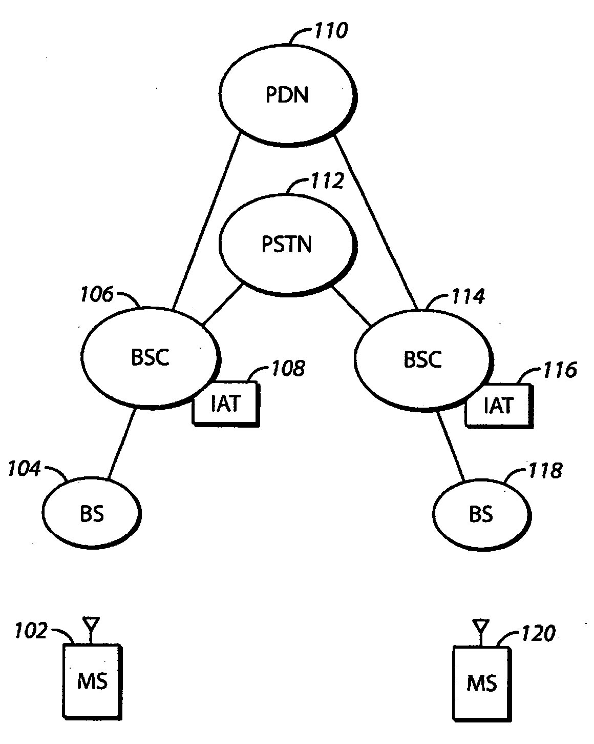
[0010] A system and method for setting the inactivity timer in a mobile communication system determines the expiration period of the timer by examining the characteristics of messages that are exchanged within the system. The approaches described herein conserve battery power of mobile stations and result in the efficient allocation of system resources.
[0013] Thus, approaches are described herein that conserve the battery life of mobile stations while also efficiently allocating resources in the system. The splitting of calls is also reduced thereby resulting in less paging attempts being made and further conserving system resources. Since system resources are conserved in these approaches, the resources can be allocated to tasks that truly require the resources thereby further increasing system efficiency.

Problems solved by technology

This paging results in two different types of system costs: a paging interval delay, while the system waits for the target to wake up next, and paging channel load, which is the load generated on the paging channel in every sector in that paging zone while looking for that target.
However, since the length of the timer period was fixed and often set to a long period of time, resources were held for long periods even after the PTT dialog between participants had ended.
This led to inefficient resource allocation since available resources were withheld from other participants that needed the resources.
Additionally, if the expiration period were long, the mobile stations remained active and unnecessarily drained power from their battery.
While being able to change the timer period, these approaches also proved inadequate to solve the above-mentioned problems because they relied on traffic modeling of aggregate traffic loads, and this technique did not adequately predict future system behavior.
Consequently, channel resources were still not adequately conserved and unnecessary battery consumption at mobile stations was not reduced.

Method used


Image

  • System and method for programming an inactivity timer
  • System and method for programming an inactivity timer
  • System and method for programming an inactivity timer

Examples


Embodiment Construction

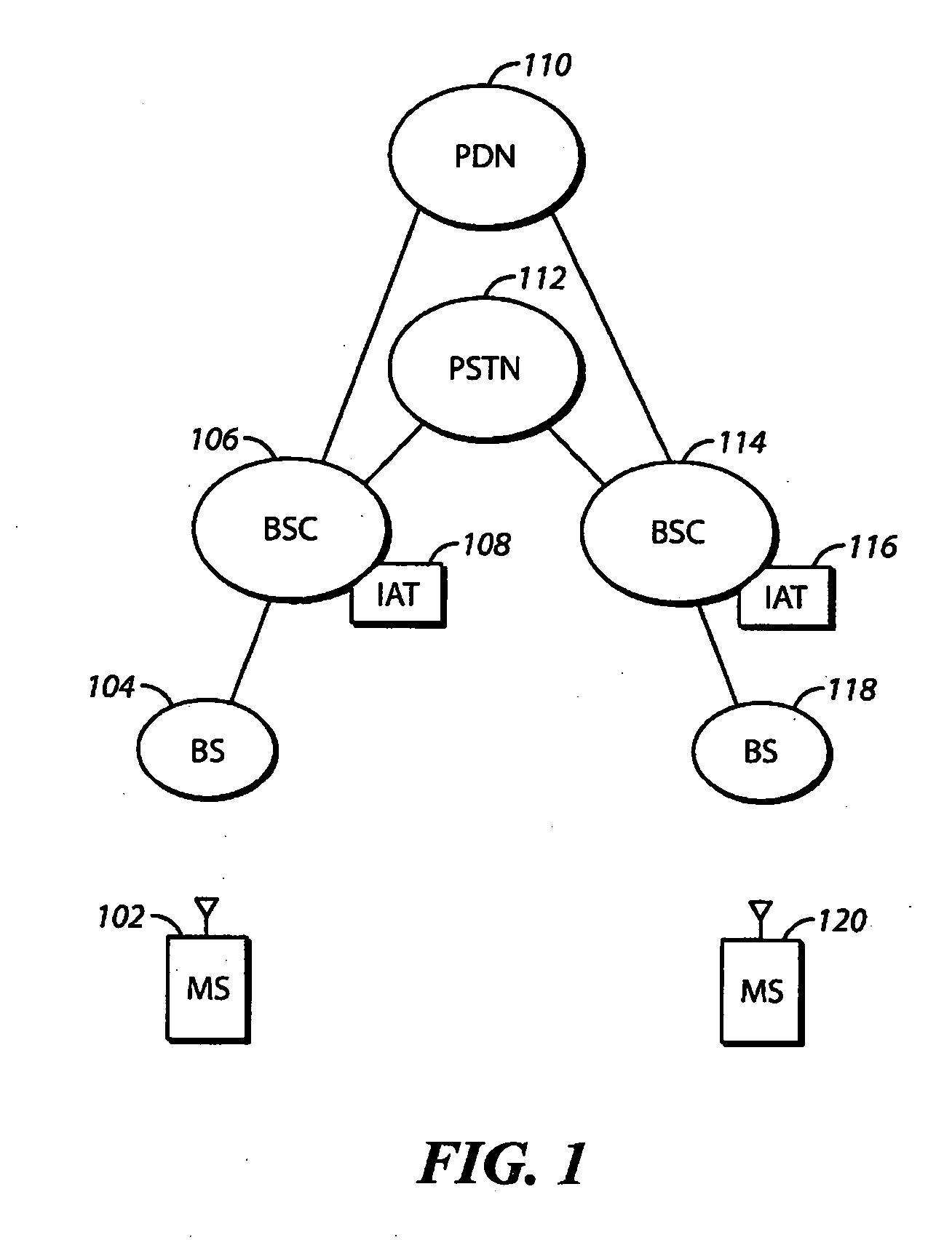
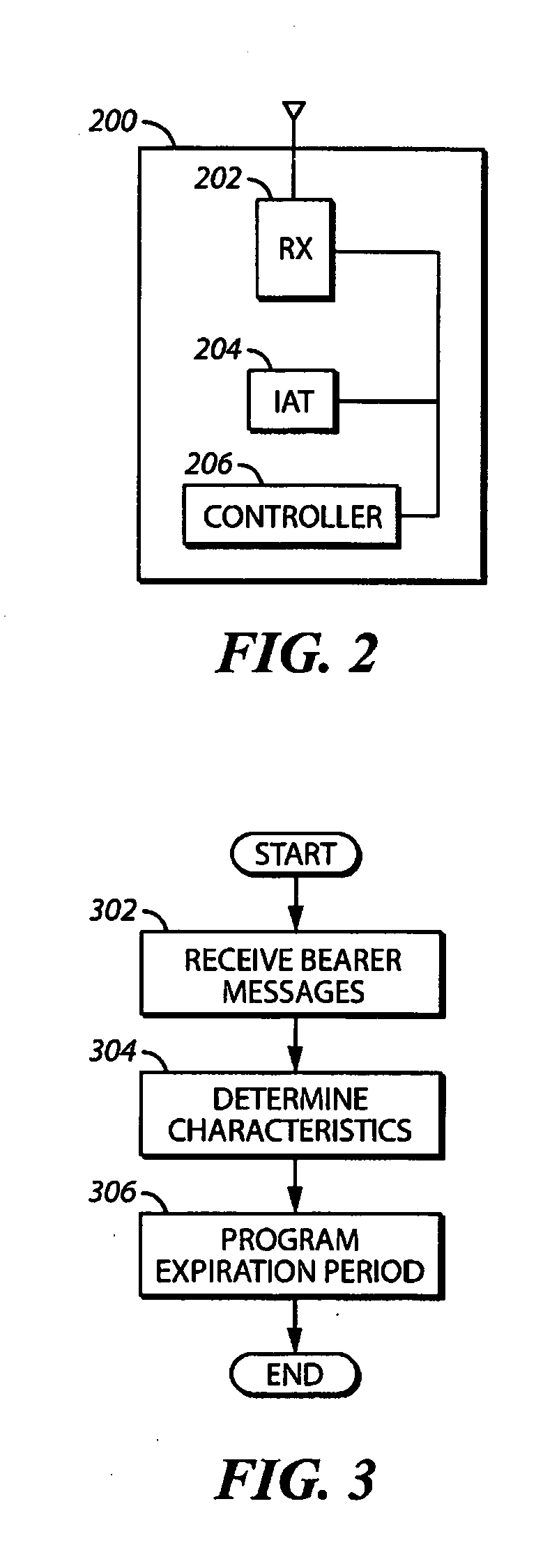
[0010] A system and method for setting the inactivity timer in a mobile communication system determines the expiration period of the timer by examining the characteristics of messages that are exchanged within the system. The approaches described herein conserve battery power of mobile stations and result in the efficient allocation of system resources.

[0011] In many of these embodiments, one or more characteristics of a PTT bearer message exchange between an originating mobile station and a target mobile station is determined. The bearer message may be part of a private call or, alternatively, a group call. An expiration period of the inactivity timer is programmed based upon the one or more characteristics of the PTT bearer message exchange. The characteristic may be the direction of a bearer message in the bearer message exchange, the relative direction between subsequent user bearer messages in message exchange, the number of bearer messages in the call, the duration and length...


PUM


Abstract

One or more characteristics of a PTT bearer message exchange between an originating mobile station (102) and a target mobile station (120) is determined. An expiration period of the inactivity timer (108) is programmed based upon the one or more characteristics of the PTT bearer message exchange.

Description

FIELD OF THE INVENTION [0001] The field of the invention relates to routing communications through networks and, more specifically, to reducing unnecessary data traffic to components of a network. BACKGROUND OF THE INVENTION [0002] In communication systems, inactivity timers measure periods of time when no events of interest occur in the system. If the timer expires with no event of interest occurring, an appropriate action may be taken. In one example of the use of an inactivity timer, when a data transfer between a mobile station and base station becomes interrupted, an inactivity timer counts down an inactivity timeout interval. Channel resources are released by the system if another data transfer between the base station and the mobile station is not initiated during this timeout interval. [0003] In Push-to-Talk (PTT) systems, a substantial percentage of calls are split when a participant becomes inactive. In many PTT systems, an inactivity timer is used to release resources aft...

Claims


Application Information

Patent Timeline
Patent Type & Authority Applications(United States)
IPC IPC(8): H04B1/38H04B7/00H04Q7/20H04W84/08
CPCH04W84/08H04W4/10H04W4/12
Inventor HARRIS, JOHN M.FERNANDEZ, SAMUEL D.
Owner MOTOROLA INC
Learn More