
Dynamically adjustable gastric implants and methods of treating obesity using dynamically adjustable gastric implants

a gastric implant and dynamic adjustment technology, applied in the field of dynamic adjustment of gastric implants and methods of treating obesity using dynamically adjustable gastric implants, can solve the problems of gastric implants and methods being susceptible to modification and alternate constructions

Inactive Publication Date: 2006-11-09
MICARDIA CORP
View PDF66 Cites 185 Cited by
  • Summary
  • Abstract
  • Description
  • Claims
  • Application Information

AI Technical Summary

Benefits of technology

"The patent describes a way to make and use gastric implants and methods. These implants and methods can be modified and constructed in different ways, as long as they still achieve the same results. The patent covers all these modifications and alternatives."

Problems solved by technology

These gastric implants and methods are, however, susceptible to modifications and alternate constructions from that discussed above that are fully equivalent.

Method used


Image

  • Dynamically adjustable gastric implants and methods of treating obesity using dynamically adjustable gastric implants
  • Dynamically adjustable gastric implants and methods of treating obesity using dynamically adjustable gastric implants
  • Dynamically adjustable gastric implants and methods of treating obesity using dynamically adjustable gastric implants

Examples


embodiment 120

[0104] Depending upon the composition of the cover, it may insulate the core so that the core is less readily able to absorb activating energy and undergo a shape change. Accordingly, in the embodiment 120 of FIG. 13 at a first end and a second end of the implant the core 122 extends beyond the cover 124 to form a first exposed core portion 126 and a second exposed core portion 128. Similarly, in the embodiment of FIG. 14, the cover 134 includes four evenly spaced openings 136 that expose short lengths of the core 132. FIG. 15 illustrates a detail view of one of the openings 136 and the core 132. The exposed portions of the core may create locations where the core is readily able to absorb activating energy, which can then be conducted along the core to the non-exposed portions. The exposed portions thus provide locations at which activation energy can be focused, which both reduces energy loss during activation and reduces the likelihood that surrounding tissue might absorb unfocus...

embodiment 250

[0118] In the embodiment 250 of FIG. 28, several different lengths of the implant are shown, and the cage-like structure of the implant is concealed by a sleeve 258. The sleeve 258 is analogous to the cover discussed above with respect to the embodiments having a shape memory core and a cover. The sleeve 258 may thus be constructed of any of the materials discussed above with respect to the cover, and share any of the same properties discussed above with respect to the cover.

[0119]FIGS. 31 and 32 illustrate one possible configuration for any of the implants disclosed herein. The implant segment 280 includes a frame 282 constructed of a material that does not have a shape memory. For example, the frame 282 could be constructed of a metal or a polymer. Along an interior surface (a surface that will contact the stomach / esophagus) the frame 282 includes band 284 of a flexible material. For example, the band 284 could be constructed of silicone rubber. Disposed just behind the band is a ...


PUM


Abstract

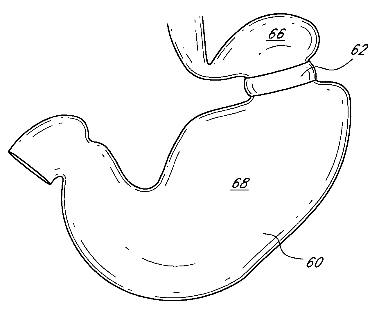
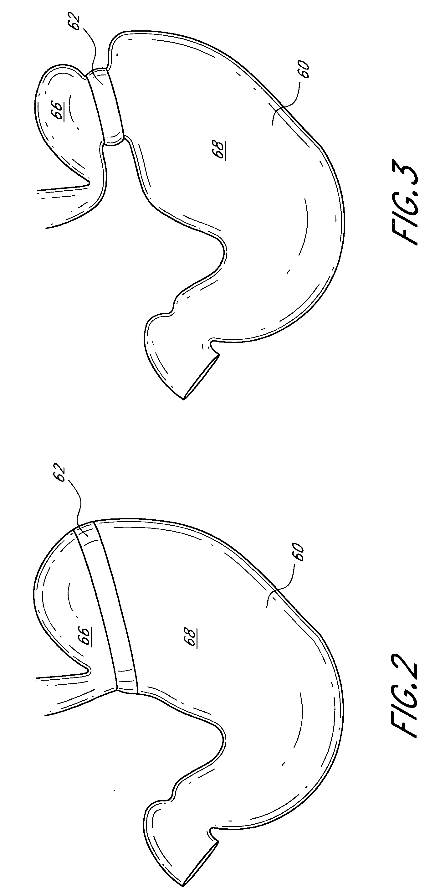
Implants for treatment of obesity may be placed within the stomach and / or esophagus or around the outside surface of the stomach and / or esophagus. The implants comprise at least a portion constructed of a shape memory material. The implants are thus adapted to be implanted in a deformed shape, and then to be transformed through the application of activation energy into a memorized shape. The shape and / or size transformation induces a change in shape of the stomach and / or esophagus, thus altering the normal digestive path of food entering the patient's gastrointestinal tract.

Description

CROSS-REFERENCE TO RELATED APPLICATIONS [0001] This application claims priority to provisional application Ser. No. 60 / 652,133, filed on Feb. 11, 2005, provisional application Ser. No. 60 / 652,466, filed on Feb. 11, 2005, and provisional application Ser. No. 60 / 701,805, filed on Jul. 22, 2005. The entire contents of each of the priority applications are hereby incorporated by reference.BACKGROUND OF THE INVENTION [0002] 1. Field of the Invention [0003] The present invention relates to a system and method for dynamically reshaping and resizing the stomach and / or esophagus using an implant or implants within or around the outside of the stomach and / or esophagus and externally or internally activating the implant(s) to induce a change in shape and / or size of the implant(s). [0004] 2. Description of the Related Art [0005] Bariatrics is the branch of medicine concerned with the management of obesity and allied diseases. There are two main categories of bariatric surgery techniques availab...

Claims


Application Information

Patent Timeline
Patent Type & Authority Applications(United States)
IPC IPC(8): A61F2/00A61B17/08A61F13/00
CPCA61F5/0053A61F2002/044A61F5/0086A61F5/0079
Inventor LEMBO, NICHOLAS J.MOADDEB, SHAWNSHAOULIAN, EMANUELSHAOLIAN, SAMUEL M.HENSON, MICHAEL R.
Owner MICARDIA CORP
Learn More