Annular discharge based transient state plasma igniter

A plasma point, annular discharge technology, applied in the direction of engine ignition, machine/engine, engine components, etc., can solve the problems of increasing the ignition area, unfavorable discharge, reducing power supply requirements, etc., to achieve large ignition area, small breakdown voltage, Conducive to the effect of igniting the mixture

Active Publication Date: 2013-02-06
AIR FORCE UNIV PLA
View PDF7 Cites 37 Cited by
  • Summary
  • Abstract
  • Description
  • Claims
  • Application Information

AI Technical Summary

Problems solved by technology

[0010] In order to overcome the deficiency that the transient plasma igniter in the prior art is not conducive to discharge at low voltage, reduce the re

Method used


Image

  • Annular discharge based transient state plasma igniter
  • Annular discharge based transient state plasma igniter
  • Annular discharge based transient state plasma igniter

Examples


Embodiment 1

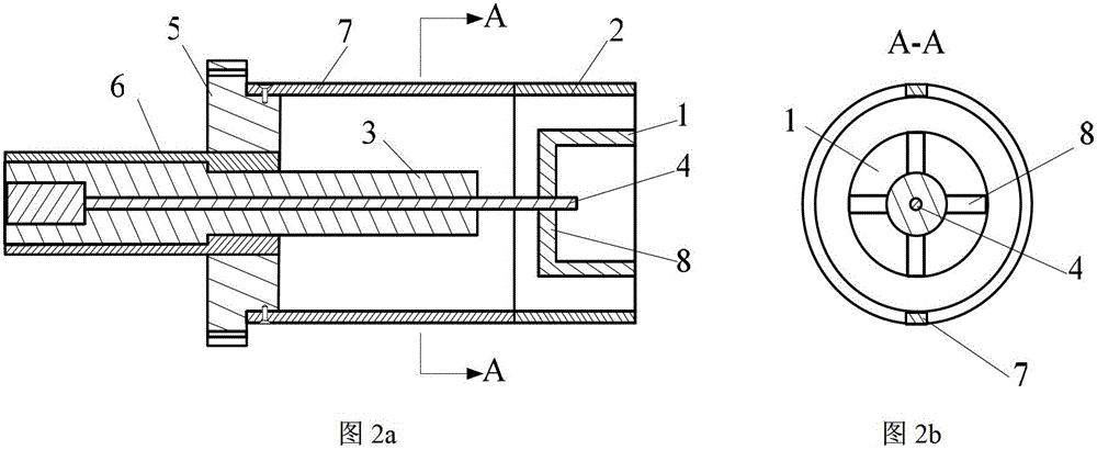
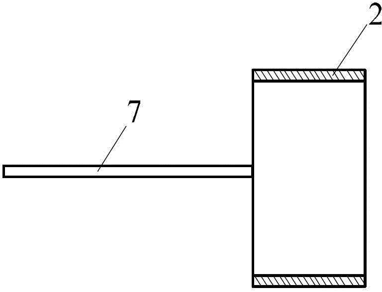
[0032] This embodiment is a transient plasma igniter based on annular discharge, which is used for ignition of internal combustion engines, including anode 1, cathode 2, insulating sleeve 3, anode conducting rod 4, fixing seat 5, insulating protective sleeve 6 and cathode connection pole 7. as attached figure 2 shown. A pair of cathode connecting rods 7 protruding axially are symmetrically distributed on the end surface of one end of the cathode 2 , and the other ends of the two cathode connecting rods 7 are fixed on the outer circular surface of the fixing seat 5 . The anode 1 is located inside the cathode 2 . One end of the insulating protective sheath 6 is located in the inner hole of the fixing seat 5 . The insulating sleeve 3 is installed in the inner hole of the insulating protective sleeve 6 , and one end of the insulating sleeve 3 extends between the two cathode connecting rods 7 of the cathode 2 .

[0033] The anode 1 is annular and made of high temperature resis...

Embodiment 2

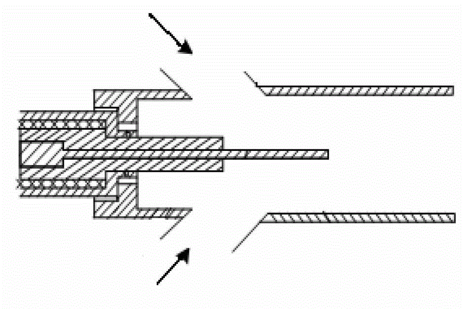
[0044] This embodiment is a transient plasma igniter based on annular discharge applied to a pulse detonation engine, including an anode 1, an insulating sleeve 3, an anode conducting rod 4, an insulating protective sleeve 6, a cross rib 8, and a detonation tube 9. The air intake hole 10 and the fixing seat 5. structure as attached Figure 7 shown.

[0045] In this embodiment, the detonation tube 9 is used as the cathode, and the anode 1 is discharged and ignited. The inlet end of the detonation tube 9 is fixed on the end face of one end of the fixing base 5 by screws. One end of the insulating sheath 6 is put into the central hole of the fixing seat 5, one end of the insulating sheath 3 is put into the said insulating sheath 6, and the other end of the insulating sheath 3 penetrates into the inner hole of the detonation tube 9 middle. The anode conducting rod 4 is loaded into the insulating sleeve 3 , and the anode 1 is installed at the end of the anode conducting rod 4 l...


PUM


Abstract

The invention relates to an annular discharge based transient state plasma igniter. An insulation sleeve is located in an insulation protection sleeve, and one end of the insulation sleeve is located in a cathode. An anode conduction rod is located in the insulation sleeve, and one end of the anode conduction rod is arranged in a center hole of the cathode. One end of the insulation protection sleeve is arranged in a fixing base. The anode is located in the cathode. The transient state plasma igniter is provided with a mixed gas channel. According to the invention, high-energy nanosecond pulse is used to discharge electricity to form a local high temperature area, and a large quantity of active particles are activated to ignite combustible mixed gas in an extremely short period of time. The ignition area is large, and the mixed gas can be ignited by multiple points; the ignition time is extremely short, and the ignition delay time is shorter; the ignition energy can be well coupled with the gas mixture, macromolecule hydrocarbon fuel in the ignition area is ionized as active particles with low activation energy, so that the chemical reaction of the mixed gas is faster, the reaction time is shorter, and the ignition success rate is high.

Description

technical field [0001] The invention relates to the field of engines, in particular to a transient plasma igniter based on annular discharge. Background technique [0002] At present, the spark plug ignition method is widely used in the combustion chambers of various power plants. Spark plug ignition is based on the thermal theory of ignition. At the moment of ignition (the moment of spark plug discharge), the temperature of the mixed gas around it rises rapidly, so that the exothermic reaction in this small volume begins. [0003] The ignition energy utilization rate of the spark plug ignition process is low, only about 5% to 20% of the energy is used to heat the mixture, most of the energy is used to heat the electrode, the ignition delay time is long, and it can only be used in a small area Realize single point ignition. At present, the use of lean premixed combustion can improve the fuel economy of internal combustion engines while significantly reducing NO x , HC and...

Claims


Application Information

Patent Timeline
IPC IPC(8): F02P23/00
Inventor 于锦禄何立明丁未陈鑫孙冬杜纯
Owner AIR FORCE UNIV PLA
Why Eureka
Try Eureka