Spark plug

A technology of spark plugs and electrodes, applied in the field of spark plugs, can solve the problems of small sparks, low efficiency, and high explosion pressure of pistons, and achieve high explosion pressure, expand ignition area, and improve work efficiency

Inactive Publication Date: 2014-01-08
ZEROQ SCI & TECH
View PDF6 Cites 0 Cited by
  • Summary
  • Abstract
  • Description
  • Claims
  • Application Information

AI Technical Summary

Problems solved by technology

However, because the distance between the two electrodes is too small, the spark generated is very small relative to the volume of the combustion chamber, so it can only be ignited locally in the combustion chamber, and then spread to the entire combustion chamber for complete combustion, that is, the combustion in the combustion chamber is not carried out simultaneously. , so it is impossible to generate instantaneous high explosion pressure on the piston, resulting in low efficiency

Method used


Image

  • Spark plug
  • Spark plug
  • Spark plug

Examples


Embodiment 1

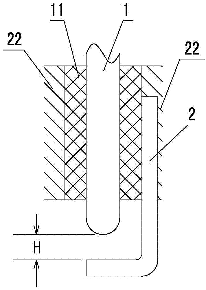
[0027] Such as figure 1 The shown spark plug includes an electrode A1 and an electrode B2, the lower end of the electrode B2 bends and extends below the electrode A1, and the distance H between the two is 1.2 mm. The electrode A 1 is fixedly connected to the casing 22 via the insulator 11 , and the electrode B 2 is fixedly connected to the casing 22 . The electrode A1 and the electrode B2 are respectively connected to two electrodes of a high voltage power supply capable of breaking down the electrode A1 and the electrode B2. In a gasoline engine, the casing 22 is fixedly connected with the machine body, the electrode A 1 discharges and breaks down the gas mixture between the electrode B 2 , discharges to the electrode B 2 to generate sparks, and achieves an ignition effect.

[0028] During specific implementation, optionally, the distance between the electrode A 1 and the electrode B 2 can be increased according to actual needs, such as 2 mm, 4 mm, 8 mm, and so on.

Embodiment 2

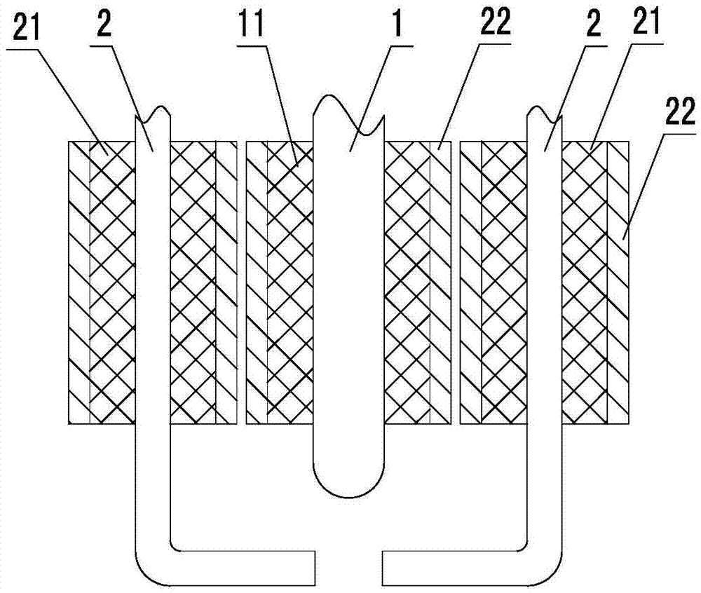
[0030] Such as figure 2 The spark plug shown is based on Embodiment 1: the electrode B 2 is fixedly connected to the housing 22 through an insulator 21, and the electrode B 2 is set to two, and the two electrodes B 2 are distributed around the electrode A1.

[0031] In practical applications, several electrodes B2 can be arranged around the electrode A1, and the electrode A1 can simultaneously discharge all the electrodes B2, generate multiple electric sparks, and increase the Large ignition area effect.

Embodiment 3

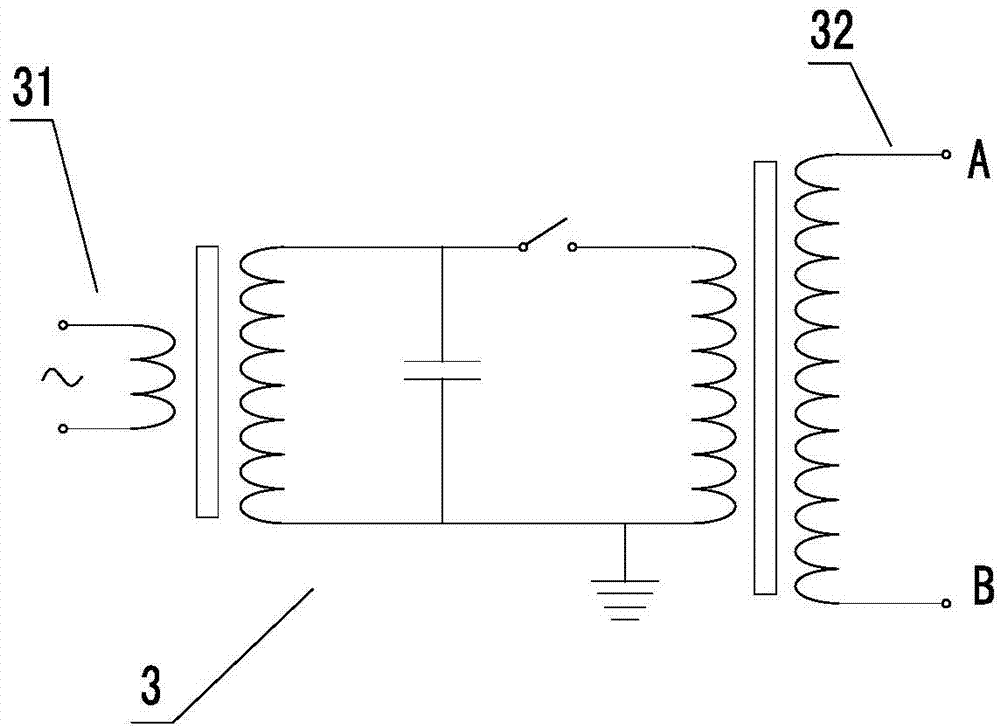
[0033] Such as image 3 In the shown Tesla coil 3, its input terminal 31 is connected to alternating current, and after the voltage rises through the two-stage transformer, the output terminal 32 outputs a voltage sufficient to break down the mixture between the electrode A1 and the electrode B2. . The electrode A1 of the spark plug in the above-mentioned embodiment 1 or embodiment 2 can be connected to the A contact point of the output end 32. When the spark plug of embodiment 1 is used, since the electrode B2 and the body are connected through The casing 22 is fixedly connected together, so the B contact of the output end 32 is selected to be connected to the body; and the engine using the spark plug of embodiment 2, since the electrode B 2 and the body are insulated, The B contact of the output terminal 32 is connected to the electrode B2.

[0034] Compared with the traditional spark plug structure, the distance between the electrode A1 and the electrode B2 increases in t...


PUM


Abstract

The invention discloses a spark plug. The spark plug comprises an electrode A and an electrode B, wherein the distance between the electrode A and the electrode B is larger than 1mm, and the electrode A and the electrode B are connected with two electrodes of a high-voltage power source which can carry out breakdown on the electrode A and the electrode B respectively. According to the spark plug, due to the fact that the distance between the electrode A and the electrode B on the spark plug is increased, the length of a discharging spark is increased, the ignition area is enlarged, the time of ignition of fuel in a whole combustion chamber is shortened, the combustion time of the fuel in an existing combustion chamber is correspondingly shortened, and higher explosion pressure can be generated for a piston, and the outward work efficiency of the piston can be improved.

Description

technical field [0001] The invention relates to the technical field of thermal energy and power, in particular to a spark plug. Background technique [0002] The spark plug is a necessary component of the gasoline engine. It uses the discharge between the electrodes to generate sparks, ignites the compressed gas mixture, and makes the gasoline engine work normally. At present, the gap between the center electrode and the side electrode of the spark plug is 0.6-0.7mm. When in use, the gas mixture in the cylinder is ignited by using the spark generated between the two due to the breakdown voltage. However, because the distance between the two electrodes is too small, the spark generated is very small relative to the volume of the combustion chamber, so it can only be ignited locally in the combustion chamber, and then spread to the entire combustion chamber for complete combustion, that is, the combustion in the combustion chamber is not carried out simultaneously. , so it i...

Claims


Application Information

Patent Timeline
Patent Type & Authority Applications(China)
IPC IPC(8): H01T13/22
Inventor 靳北彪
Owner ZEROQ SCI & TECH
Why Eureka
Try Eureka