Thermoelectric generator with micro-electrostatic energy converter

a micro-electrostatic energy converter and generator technology, applied in the direction of thermoelectric devices with peltier/seeback effect, thermoelectric devices, electric devices, etc., can solve the problems of periodic replacement of batteries, disassembly and maintenance of batteries, and provide a transient source of power, so as to improve the overall power output

Inactive Publication Date: 2009-01-29
DIGITAL ANGEL CORP
View PDF9 Cites 37 Cited by
  • Summary
  • Abstract
  • Description
  • Claims
  • Application Information

AI Technical Summary

Benefits of technology

[0014]The present invention specifically addresses and alleviates the above-mentioned needs associated with power supplies for microelectronic devices by providing a power supply that satisfies the requirement of a separate voltage source for electrostatic converters to initiate conversion of

Problems solved by technology

However, power that is supplied by batteries dissipates over time requiring that the batteries be periodically replaced.
Solar cells, although having an effectively unlimited useful life, may only provide a transient source of power as the sun or other light sources may not always be available.
The movement as a result of vibration acting against the electric field between

Method used


Image

  • Thermoelectric generator with micro-electrostatic energy converter
  • Thermoelectric generator with micro-electrostatic energy converter
  • Thermoelectric generator with micro-electrostatic energy converter

Examples


Embodiment Construction

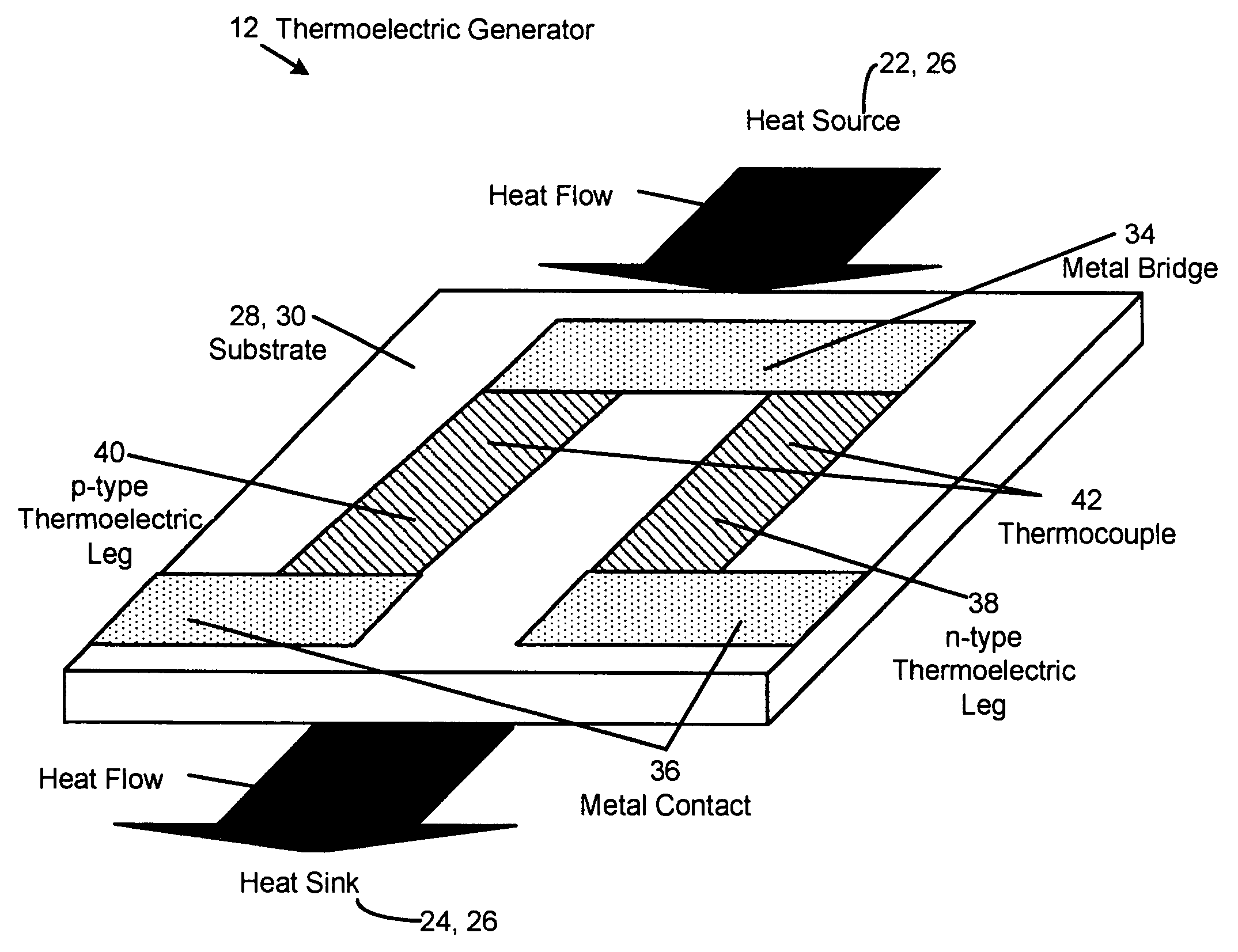
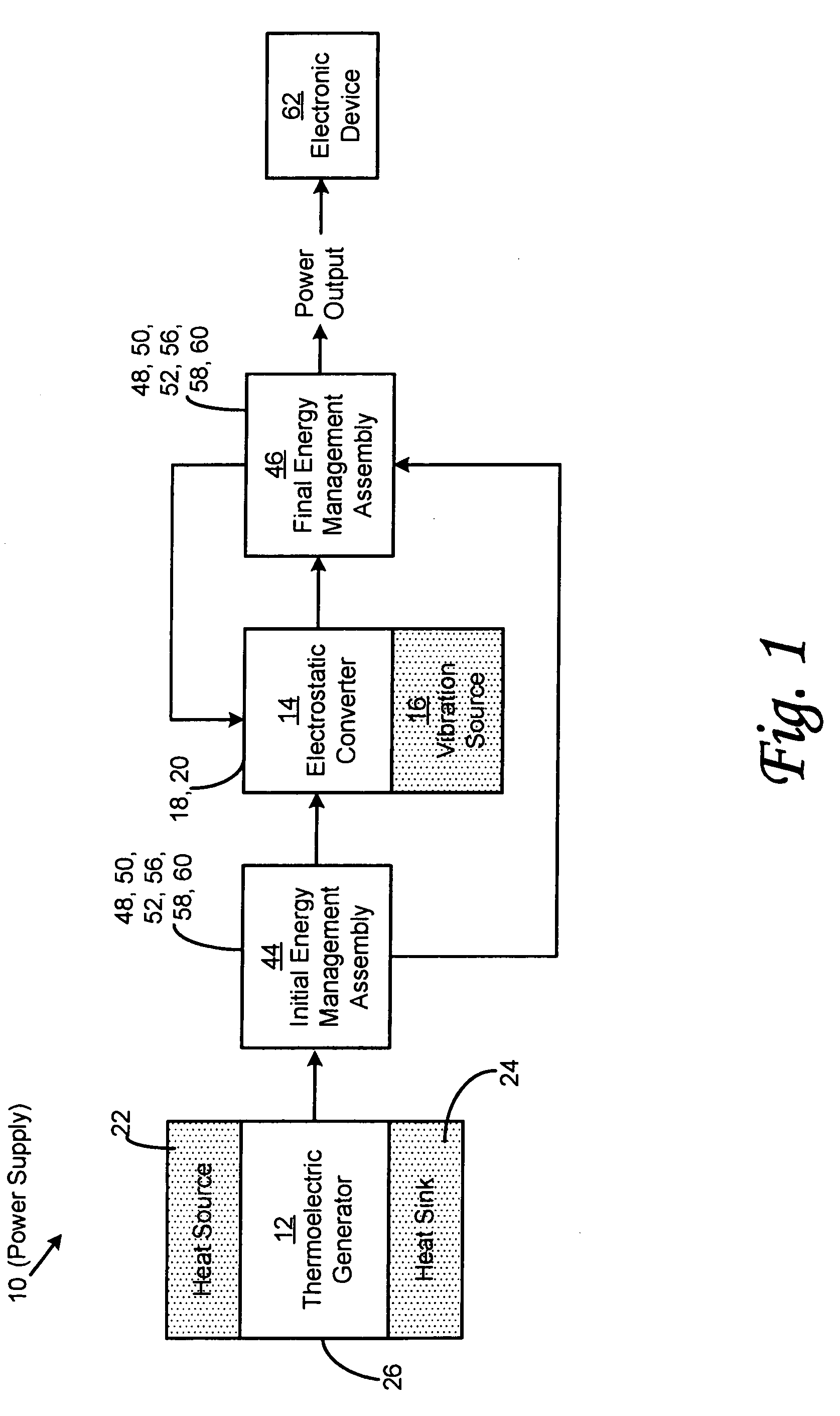
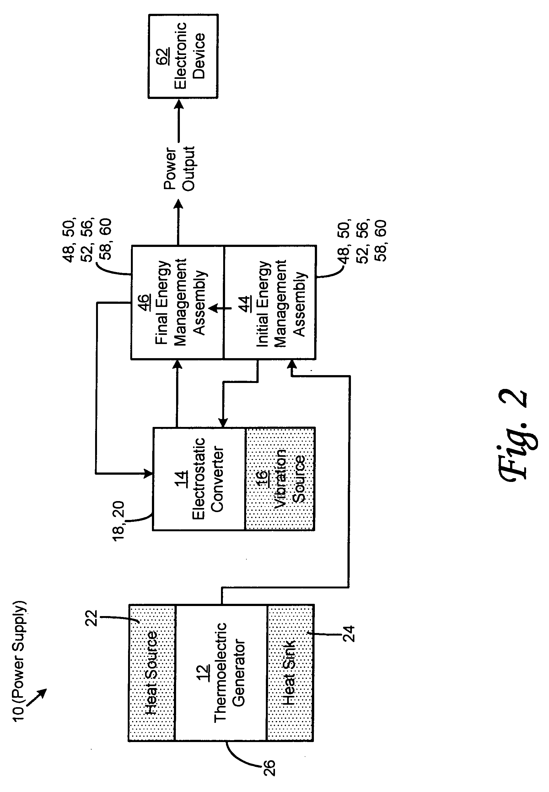
[0024]Referring now to the drawings wherein the showings are for purposes of illustrating preferred embodiments of the present invention and not for purposes of limiting the same, shown in FIG. 1 is a schematic diagram of a power supply 10 that is specifically adapted to convert mechanical energy into electrical energy. Advantageously, the power supply 10 of the present invention is adapted to produce a relatively stable and continuous supply of electrical energy sufficient to power microelectronic devices and sensor systems.

[0025]In its broadest sense, the power supply 10 comprises a thermoelectric generator 12, an initial energy management assembly 44, an electrostatic converter 14, and a final energy management assembly 46. Thermoelectric generator 12 is adapted to generate an electrical activation energy with sufficiently high voltage in response to a temperature gradient acting across the thermoelectric generator 12. The initial energy management assembly 44 is connected to the...


PUM


Abstract

A power supply comprises a thermoelectric generator, an initial energy management assembly, an electrostatic converter and a final energy management assembly. The thermoelectric generator is adapted to generate an electrical activation energy with sufficiently high voltage in response to a temperature gradient acting across the thermoelectric generator. The initial energy management assembly is connected to the thermoelectric generator and is adapted to receive and condition the electrical activation energy produced by the thermoelectric generator. The electrostatic converter is connected to the initial energy management assembly and is activatable by the electrical activation energy received therefrom and is configured to generate electrical energy in response to vibrational energy acting thereupon. The final energy management assembly is connected to the electrostatic converter and is adapted to condition the electrical energy produced thereby.

Description

CROSS-REFERENCE TO RELATED APPLICATIONS[0001]The present application claims priority to co-pending U.S. Provisional Application No. 60 / 809,479 entitled THERMOELECTRIC GENERATOR WITH MICOELECTROSTATIC ENERGY CONVERTER filed on May 31, 2006, the entire contents of which is expressly incorporated by reference herein. The present application is also related to U.S. patent application Ser. No. 11 / 352,113 filed on Feb. 10, 2006 and entitled Improved Low Power Thermoelectric Generator, which is a continuation-in-part application of U.S. application Ser. No. 11 / 185,312, filed on Nov. 17, 2005 and entitled Low Power Thermoelectric Generator, which is a continuation application of U.S. application Ser. No. 10 / 440,992 filed on May 19, 2003 and entitled Low Power Thermoelectric Generator, now U.S. Pat. No. 6,958,443, the entire contents of each being expressly incorporated by reference herein.STATEMENT RE: FEDERALLY SPONSORED RESEARCH / DEVELOPMENT[0002](Not Applicable)BACKGROUND[0003]The present...

Claims


Application Information

Patent Timeline
IPC IPC(8): H01L35/30H01L35/04
CPCH01L35/32B81B3/0032H10N10/17
Inventor STARK, INGO
Owner DIGITAL ANGEL CORP
Why Eureka
Try Eureka