Buffering in streaming delivery

a streaming and buffering technology, applied in the field of buffering packets of media streams, can solve the problems of packet loss, inability to guarantee the compatibility of the buffer model of the media decoder, packet loss,

Inactive Publication Date: 2006-11-09
NOKIA TECHNOLOGLES OY
View PDF17 Cites 45 Cited by
  • Summary
  • Abstract
  • Description
  • Claims
  • Application Information

AI Technical Summary

Benefits of technology

[0017] Clause 13 of ETSI EN 301 192 v1.4.1 specifies the decoder model for DVB data broadcasting. The model consists of a transport buffer and an optional main buffer. The transport buffer is a small (512-byte) buffer to remove duplicates of MPEG-2 TS packets. The main buffer is used to smooth the bitrate to be suitable for media decoders. The operation of the main buffer can be controlled by specifying the output byte rate in the smoothing_buffer_descriptor syntax structure of MPEG-2 systems. However, there is no mechanism to signal and apply an initial buffering delay in the main buffer, and therefore the main buffer is unsuitable to be used in combination with MPE FEC decoding.

Problems solved by technology

It may happen that some of the packets get lost for some reason during the transmission.
For example, the transmission channel may be affected by disturbances which may weaken the signals which carry the packet stream and cause losses to the packet stream.
Otherwise, compatibility to the media decoder buffer model cannot be guaranteed.
This would consequently cause a pause in the playback.
However, this is will not be the case due to some of the following reasons:
Second, scheduling of time-slicing bursts may not be as accurate as required in the formula above, but it is likely to follow average bitrates of the stream and the time-slicing burst interval derived from the average bitrate.
Meeting an accurate bit budget for each IP stream within a time slice is a challenging target for varying-bitrate media such as video.
As a summary, initial buffering of one MPE FEC frame entirely is not a sufficient condition to guarantee pauseless decoding and playback.
However, there is no mechanism to signal and apply an initial buffering delay in the main buffer, and therefore the main buffer is unsuitable to be used in combination with MPE FEC decoding.
Therefore, the maximum buffer occupancy level may vary in different implementations, and consequently it would be problematic to determine the required FEC decoding buffer size of a particular stream without a hypothetical buffer model.

Method used


Image

  • Buffering in streaming delivery
  • Buffering in streaming delivery
  • Buffering in streaming delivery

Examples


Embodiment Construction

[0138] In the following a system according to an example embodiment of the present invention is described in more detail with reference to FIGS. 1 and 6.

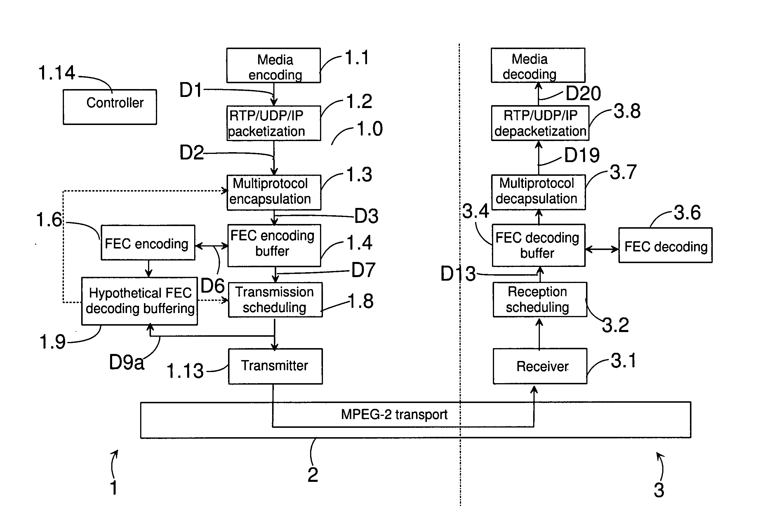
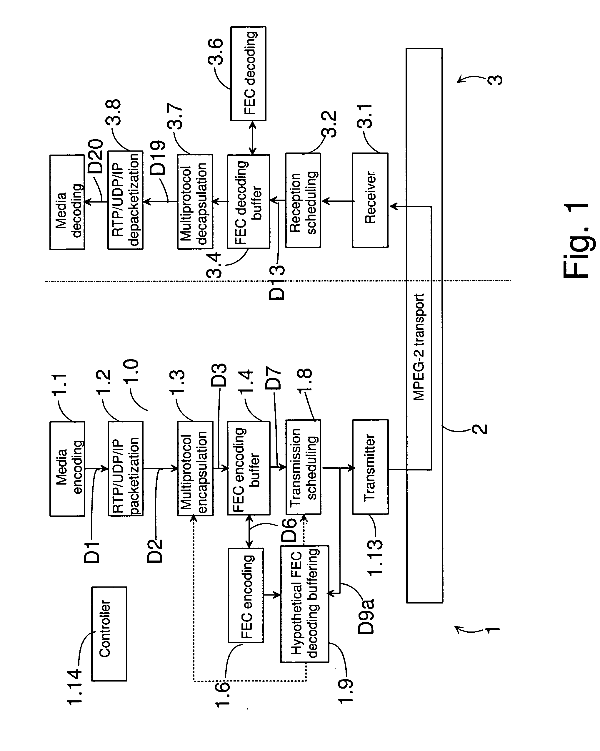
[0139] The system of FIG. 1 comprises a transmitting device 1, a transmission channel 2 and a receiving device 3. The transmitting device 1 can be e.g. a server, a wireless communication device, a personal computer etc. The receiving device 3 can be e.g. a wireless communication device, a personal computer, a TV etc.

[0140] The transmitting device 1 comprises a stream generator 1.0 for forming transport streams 702 from one or more DVB service 703 (containing media components or other IP streams). In this embodiment the stream generator 1.0 comprises an encoder 1.1 for encoding the media information when necessary, an RTP / UDP / IP packetizer 1.2, a multiprotocol encapsulator 1.3, an FEC encoding buffer 1.4, an FEC encoder block 1.6, and a transmission scheduling block 1.8. The encoder 1.1 creates a data flow D1, which contains an enc...


PUM


Abstract

Buffering packets of a media stream for transmission from a transmitting device to a receiving device. Media packets are formed from at least one kind of media information in a stream generator; at least one transmission frame is generated on the basis of media packets to be transmitted; packets to be transmitted are formed from the at least one transmission frame; and a transmission schedule is generated for packets to be transmitted. In addition, a first step and a second step of hypothetical decoding are also performed. The first step of hypothetical decoding is performed according to the transmission schedule and comprises buffering the packets to be transmitted according to the transmission schedule to a first hypothetical decoding buffer; and outputting packets from the first hypothetical decoding buffer on a transmission frame basis. The second step of hypothetical decoding comprises controlling the buffer occupancy level of the first hypothetical decoding buffer and the second hypothetical decoding buffer by controlling at least one of the following: the operation of the stream generator; the generation of at least one transmission frame; the transmission schedule.

Description

CROSS-REFERENCE TO RELATED APPLICATION [0001] This application claims priority from U.S. Provisional Patent Application No. 60 / 669,580 filed Apr. 7, 2005.FIELD OF THE INVENTION [0002] The invention relates to buffering packets of a media stream for transmission from a transmitting device to a receiving device. The invention also relates to a system, a transmitting device, a receiving device, a server, a wireless communication device, a signal, a gateway device, and a computer program product. BACKGROUND OF THE INVENTION [0003] Transmission of media information such as audio signal, video signals, still images etc. is typically based on packetization i.e. information to be transmitted is framed into packets. The packets are then transmitted as one or more packet streams. The packet streams can be transmitted e.g. as RTP (Real Time Protocol) packets or as packets of an other protocol which are not necessarily RTP packets. It may happen that some of the packets get lost for some reason...

Claims


Application Information

Patent Timeline
Patent Type & Authority Applications(United States)
IPC IPC(8): G06F15/16H04H1/00H04H60/06H04L67/01H04N7/24H04N19/89
CPCH04H60/06H04L65/608H04L12/5693H04L29/06027H04L47/10H04L47/30H04L47/56H04L49/90H04L49/9094H04N21/23406H04N21/2381H04N21/2383H04N21/2402H04N21/4382H04N21/44004H04N21/64315H04N21/64322H04N21/64738H04L65/607H04L1/0041H04L47/50H04L65/65H04L65/70H04N7/24H04W28/14H04W72/12H04L65/1101
Inventor HANNUKSELA, MISKA
Owner NOKIA TECHNOLOGLES OY
Why Eureka
Try Eureka