
Graphical messaging system

a messaging system and graphical technology, applied in the field of graphical messaging system, can solve the problems of inability to listen to the attachment, inefficient method, inability to easily transmit audio messages via e-mail, etc., and achieve the effect of facilitating the sending and receiving of messages

Inactive Publication Date: 2006-11-09
WHAT PEOPLE LOVE
View PDF14 Cites 271 Cited by
  • Summary
  • Abstract
  • Description
  • Claims
  • Application Information

AI Technical Summary

Benefits of technology

[0033] The invention provides a system for displaying a message section on a computer screen, including a plurality of client computer systems configured to: display a plurality of graphics, each having a graphic representing at least one recipient and having an information portion which has a plurality of functions, on a computer screen; enable a user to pick one of the functions; displa

Problems solved by technology

Audio messages cannot be easily transmitted via e-mail.
This is an inefficient method because it involves various software programs.
Also, the receiver of a message may not have the capability to listen to the attachment if he / she does not have the correct corresponding software.
The attachment files may also be too large to efficiently send via e-mail.
E-mail also lacks to a large degree any emotional feeling a sender wishes to impart with his / her message.
Telephone systems are also inefficient when a user wishes to contact a group of contacts with the same message.
Telephone messaging also does not offer a user-friendly method to keep a historical record of all phone messages.

Method used


Image

  • Graphical messaging system
  • Graphical messaging system
  • Graphical messaging system

Examples


Embodiment Construction

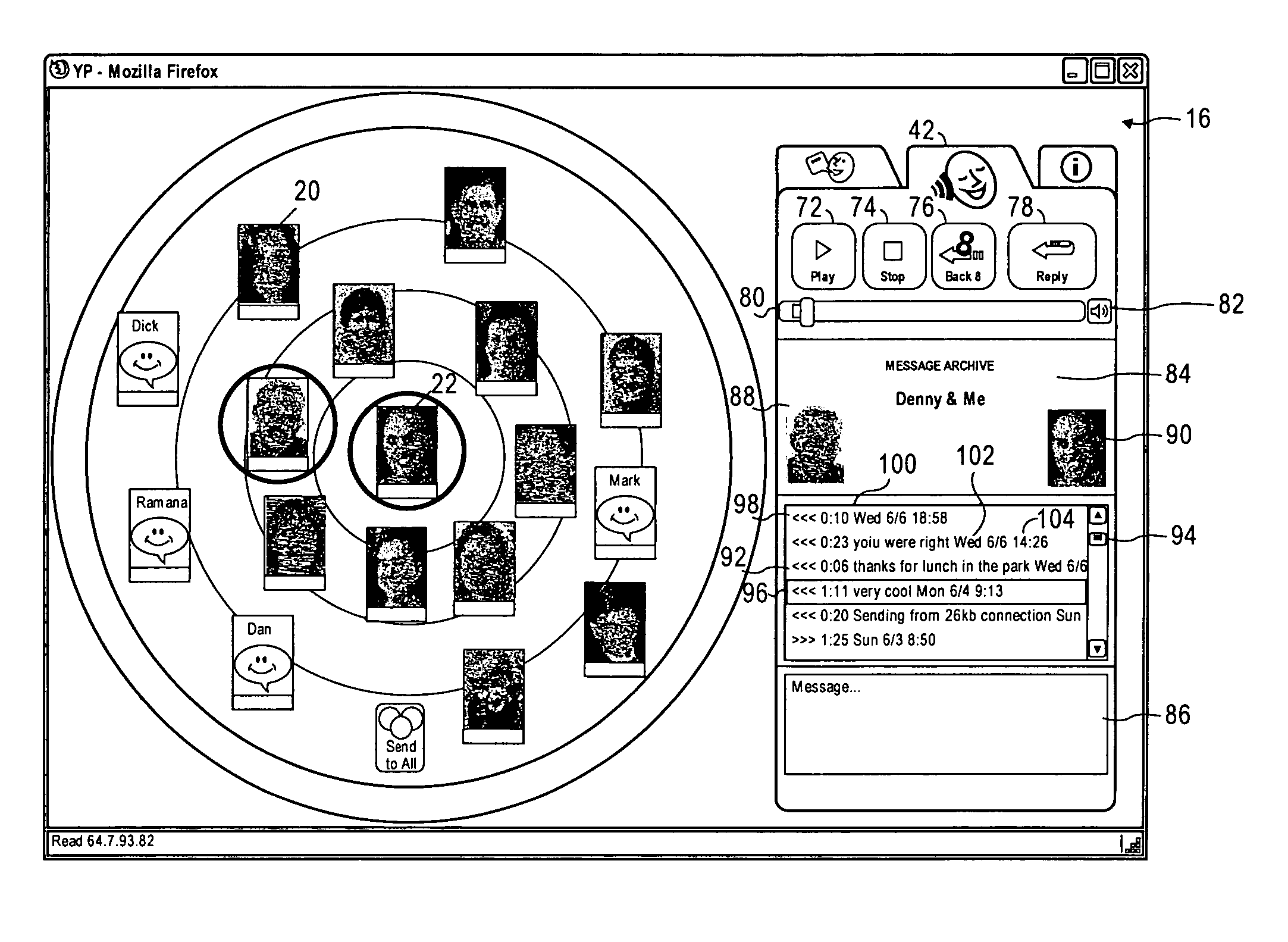
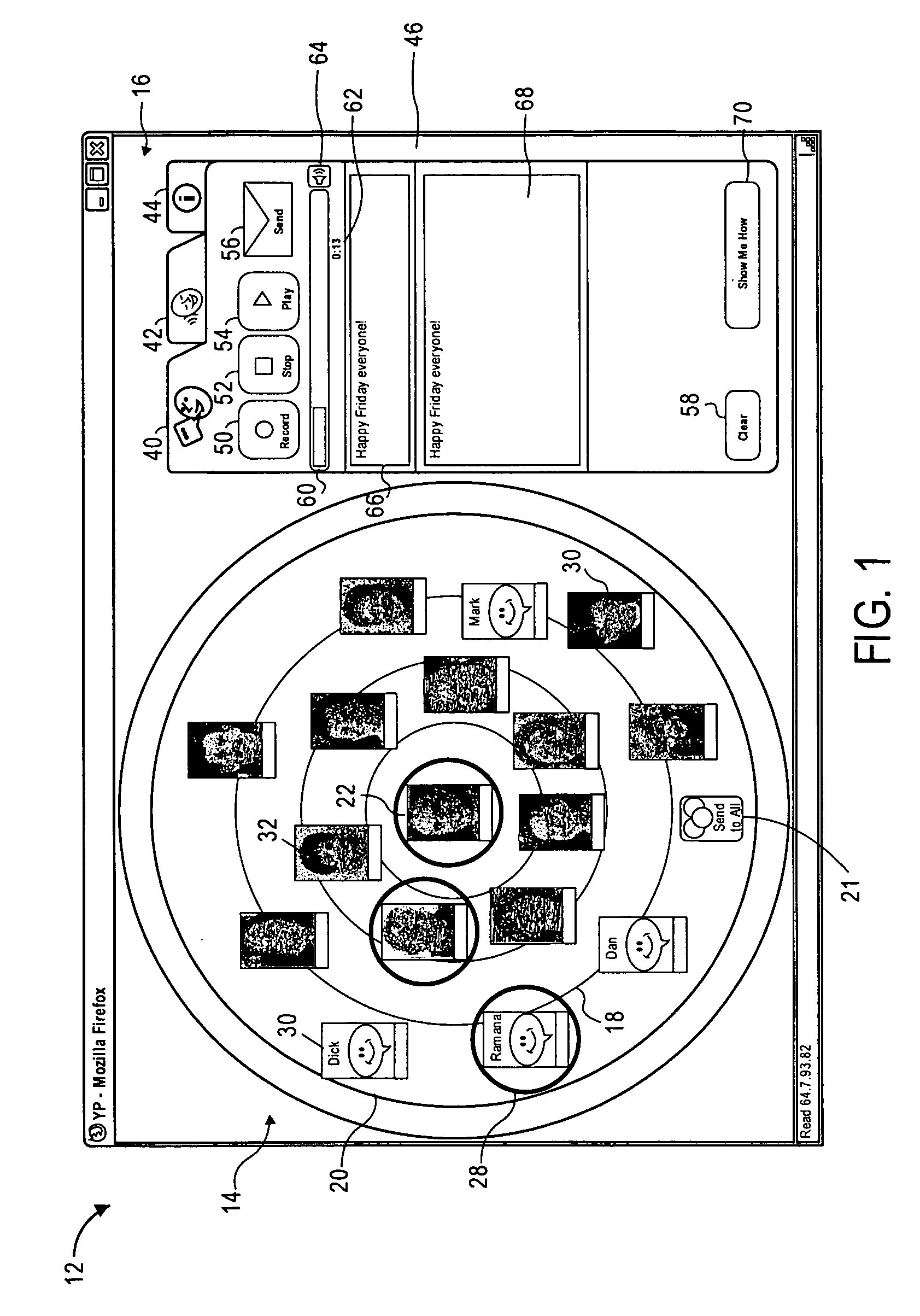
[0046]FIG. 1 of the accompanying drawings illustrates a computer screen displaying a rectangular communication interface 12 according to an embodiment of the invention, which includes a larger round contacts area 14 on the left and a smaller rectangular communication area 16 on the right.

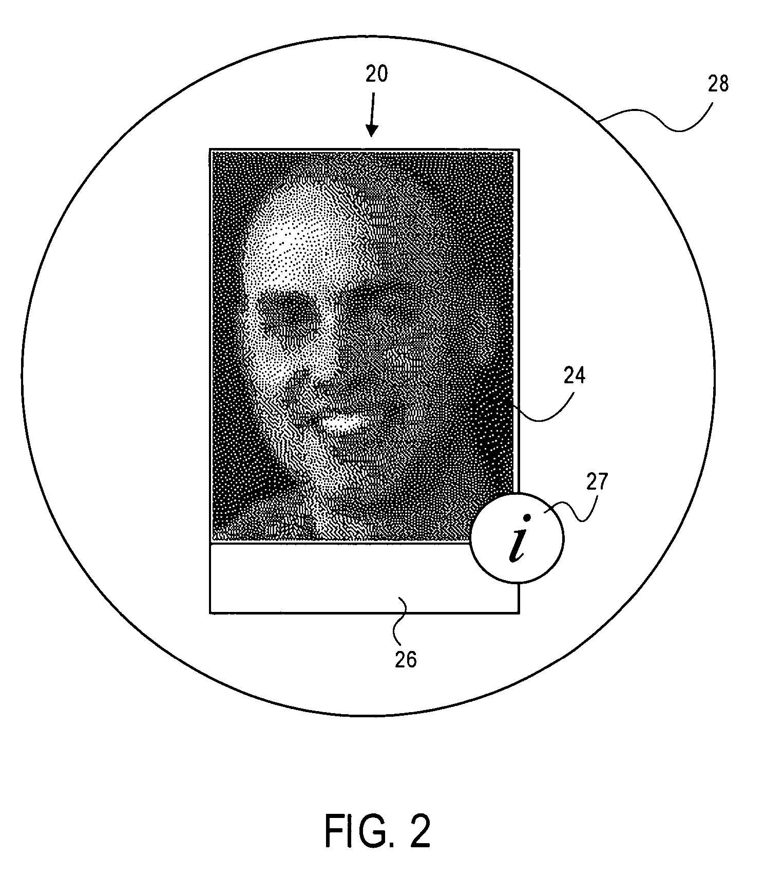
[0047] The contacts area 14 includes a plurality of concentric circles 18, multifunction icons 20, and a send-to-all icon 21. Each graphic represents a respective contact. The multifunction icons 20 are arranged in orbit patterns. Placement of the multifunction icons 20 is related to frequency of communication; graphics placed nearer the center of the contacts area 14 are used more. Placement of the multifunction icons 20 can be done automatically, as a user may place the multifunction icons 20 in any decided location. A center-positioned icon 22 represents the local user. The send-to-all icon 21 is reserved in the outermost orbit in the six o'clock position.

[0048] As illustrated in FIG. 1, each o...


PUM


Abstract

A method and system is described herein for messaging on a computer using a communications interface. The communications interface includes a section which displays graphics representing receivers and senders of messages. The communications interface also includes a section which facilitates the user to create, send, receive, and archive messages. Messages are created from audio or typed inputs from the user. A user communicates with other users over a network, such as the Internet.

Description

CROSS-REFERENCE TO RELATED APPLICATIONS [0001] This is a continuation-in-part of prior U.S. patent application Ser. No. 10 / 659,580, filed on Sep. 9, 2003, and priority is claimed from U.S. Provisional Patent Application No. 60 / 717,945 filed on Sep. 16, 2005, each of which is incorporated herein by reference in its entiretyBACKGROUND OF THE INVENTION Discussion of Related Art [0002] Electronic communication over networks, such as telephones, is well-known. Recently computer networks have been used to facilitate communication between computer users. E-mail is a common method of communication between computer users. [0003] E-mail commonly uses a communication interface displayed on a computer screen. Typically the user enters an e-mail address of a recipient. The user can then type a message and send it to the recipient. [0004] E-mail is a text-based messaging system. Audio messages cannot be easily transmitted via e-mail. Currently the only method is to save an audio message with a di...

Claims


Application Information

Patent Timeline
IPC IPC(8): G06F17/00
CPCG06F3/0481G06Q10/107G06Q10/10
Inventor FOGG, BRIAN J.
Owner WHAT PEOPLE LOVE
Features
  • Generate Ideas
  • Intellectual Property
  • Life Sciences
  • Materials
  • Tech Scout
  • Unparalleled Data Quality
  • Higher Quality Content
  • 60% Fewer Hallucinations
Learn More