Manual fruit slicer with interchangeable cutting and coring disks

a fruit slicer and interchangeable technology, applied in the field of manual fruit slicers, can solve the problems of finger touching injury, broken or rust, edges abraded, etc., and achieve the effect of reducing the possibility of injury and dividing fruit into slices

Inactive Publication Date: 2006-11-16
CHANG MING SHIH
View PDF7 Cites 29 Cited by
  • Summary
  • Abstract
  • Description
  • Claims
  • Application Information

AI Technical Summary

Benefits of technology

[0018] The present invention a manual fruit slicer with interchangeable cutting and coring disks has a separable base and a disk. In use, the disks can be changed as desired. While combining a base and a disk to form a manual fruit slicer, a force is exerted to divide the fruit into slices more easily, as one of the different disks is chosen and combined to form a set of useable straight edges with a central edged coring circlet at any time, the fruits can be processed through and divided into bulky lumps, small slices, pieces, or cubes with the different cores of fruits cropped out as desired. After using, a disk is detachable and can be combined to the base in an opposite direction, thus achieves a secured decoration of the reversed-edges to avoid straight edges from directly exposing outward.
[0019] Secondly, handles projected out from the outer wall of a disk are suitable for both two hands of the user to hold and operate, when changing and combining the chosen one from the two or more different disks, it can be used to lower the possibility of injuries as the users' fingers to touch the edges unintentionally.

Problems solved by technology

A conventional manual fruit slicer has the edges exposed outward, while the edges being touched by the user erroneously leads to possible injuries occurred to the users' touching fingers.
Even the slicer is placed or stacked with the plates and bowls together, the edges are easy to clash against the plate or bowl inflicted the edges abraded, broken or rust.

Method used


Image

  • Manual fruit slicer with interchangeable cutting and coring disks
  • Manual fruit slicer with interchangeable cutting and coring disks
  • Manual fruit slicer with interchangeable cutting and coring disks

Examples


first embodiment

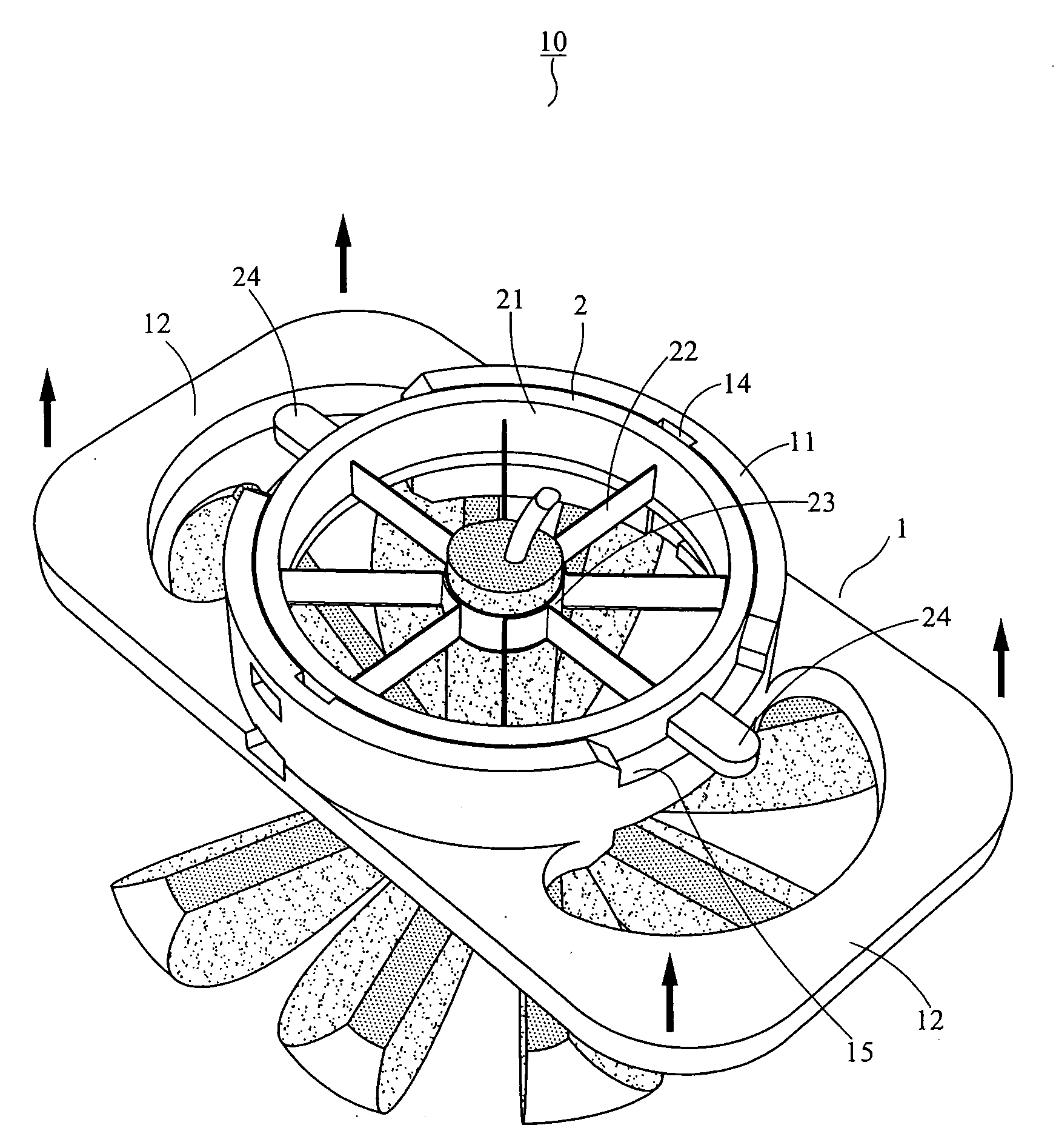
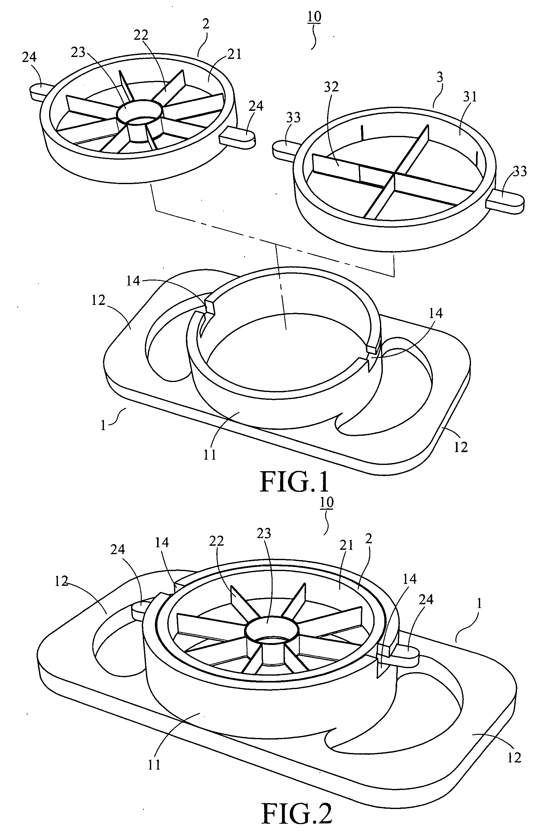
[0023] With reference to FIG. 1, an exploded perspective view of the first embodiment of the present invention is illustrated. Manual fruit slicer 10 comprises a base 1, a disk 2 or 3.

[0024] Said base 1 has a hollowed annular sleeve 11 protruded out from the base at its center with two laterally extended jug-ears at both ends, two L-type grooves 14 are formed on each side beside the opening of the hollowed annular sleeve 11, two L type grooves 14 are shaped in the opposite direction and distributed in symmetry with each other. At this place, L type grooves 14 are formed through a wall of the annular sleeve 11 beside the opening, and the entry portion of the L type groove is shaped in opened up mode.

[0025] Said disks are grouped into two kinds of edges. Illustrated on the left side of the FIG. 1, a disk 2 comprises an annular edge frame 21 (i.e. an inner circle) with a central hollowed circlet 23, and a plurality of straight edges 22 (it is exemplified as eight edges) distributed i...

second embodiment

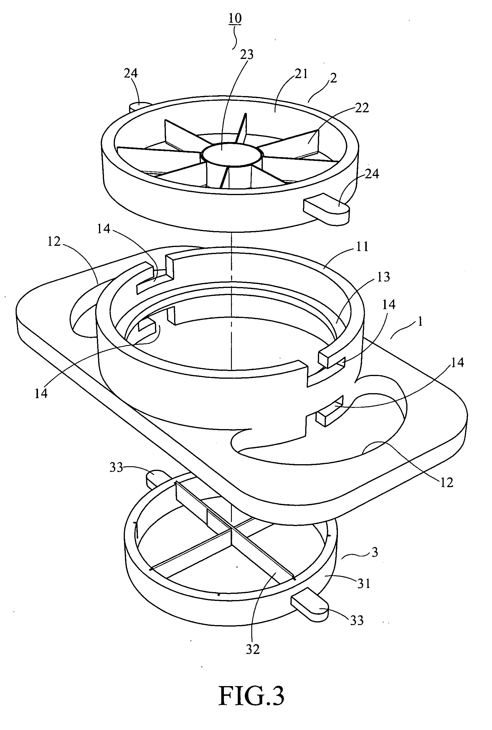
[0028] With reference to FIG. 3, an exploded perspective view of the second embodiment of the present invention is shown. A manual fruit slicer 10 comprises a base 1 and upper, lower disks 2,3. After combination, the assembled structure of the manual fruit slicer 10 is shown as the FIG. 4.

[0029] The second embodiment is different from the first embodiment. In the second embodiment, such as an annular flange 13 bulged out along the centerline of the inner wall of the hollowed annular sleeve 11. Thus the inner wall of sleeve 11 is divided into upper and lower sections. Both upper and lower sections have opening, both sides of the upper and lower sections beside the openings have top end, and L type grooves 14 are formed through the top ends in the opposite direction in symmetry.

[0030] Said disks 2,3 are illustrated in FIG. 1. As a disk 2 being put into the upper section of the hollowed annular sleeve 11, it has a pair of handles 24 bulged out from the outer wall of the disk 2, which...

third embodiment

[0032] With reference to FIG. 6, an exploded perspective view of the third embodiment of the present invention is shown. A manual fruit slicer 10 comprises a base 1 and disks 2,3. An assembled view of the manual fruit slicer is shown as FIG. 7.

[0033] In FIGS. 6 and 3, there have the same base 1 for adding components. And a hollowed annular sleeve 11 is protruded out from the base around the center with two laterally extended out jug-ears 12 at both ends. An annular flange 13 bulged out along the centerline of the inner wall of the hollowed annular sleeve 11. Thus the inner wall of sleeve 11 is divided into upper and lower sections. Both upper and lower sections have opening, both sides of the upper and lower sections beside the openings have top end. But in FIG. 6 an L type groove 14 and a concaved groove 15 separated from the L type groove are formed on each top end. In which, each pair of two L type grooves are formed in the opposite direction and distributed in symmetry. But eac...


PUM


Abstract

The present invention is aimed to provide a manual fruit slicer with interchangeable cutting and coring base. It has the practical functions as replacement of disks, reverted said edges onto the base, and a plurality of said edges can be received in the base. In use, a manual fruit slicer comprises a base, and disks. A hollowed annular sleeve is protruded out from the base around its center with two jug-ears extended out from both of its ends. A disk is designed as an annular edge frame disposed inside the hollowed annular sleeve. It is characterized by L type grooves formed through the upper or lower section being adapted to the handles protruded out from the outer wall of the disk to fix in place. The handles are also designed for a user's grip.

Description

FIELD OF THE INVENTION [0001] The present invention is related to a manual fruit slicer with interchangeable cutting and coring disks, as a manual instrument used to cut off core of fruit in addition to cut the pulp into slices simultaneously. BACKGROUND OF THE INVENTION [0002] With Reference to FIG. 14, a perspective view of a conventional manual fruit slicer is illustrated. A conventional manual fruit slicer 9 includes an annular slicing base 91 with a hollowed coring circlet 93 at its center and straight edges 92 disposed axially between the base 91 and the coring circlet 93. In that, said edges 92 and coring circlet 93 are combined by welding, fusing or other means, and then put the edges-circlet semi-finished instrument into a mold, being engaged with an injection molded annular base 91 to form a manual fruit slicer 9 as a whole one. The edges 92 are secured to the annular base 91. [0003] With reference to FIG. 15, a schematic view of a conventional manual fruit slicer in use i...

Claims


Application Information

Patent Timeline
Patent Type & Authority Applications(United States)
IPC IPC(8): A21C15/04
CPCB26D3/26
Inventor CHANG, MING-SHIH
Owner CHANG MING SHIH
Why Eureka
Try Eureka