
Side supported 6-high rolling mill

a rolling mill and side support technology, applied in the direction of metal rolling arrangement, counter-pressure device, manufacturing tools, etc., can solve the problems of inability to correct more local defects, non-symmetrical quarter buckles, and room to mount cooling sprays on the work roll

Active Publication Date: 2006-11-16
T SENDERCHIMO
View PDF21 Cites 12 Cited by
  • Summary
  • Abstract
  • Description
  • Claims
  • Application Information

AI Technical Summary

Problems solved by technology

These methods are quite effective for controlling second order flatness defects such as center-buckle and wavy edge, but are not able to correct more local defects such as non-symmetrical quarter buckle and localized strip buckle.
On prior art side supported 6-high mills, not only is the work roll diameter relatively small, but the space at each side of the work rolls is filled with the side support structure and there is no room to mount work roll cooling sprays.

Method used


Image

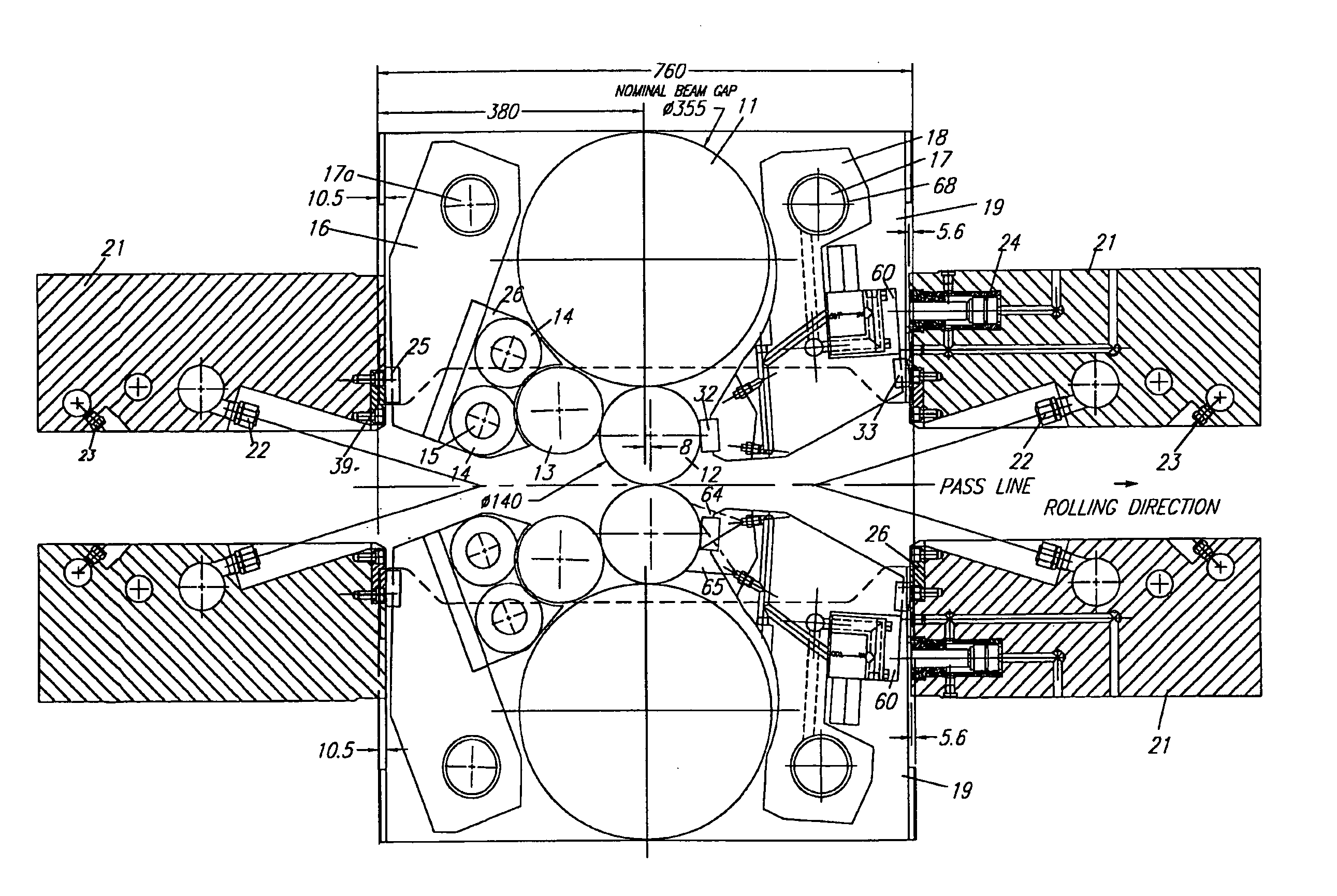
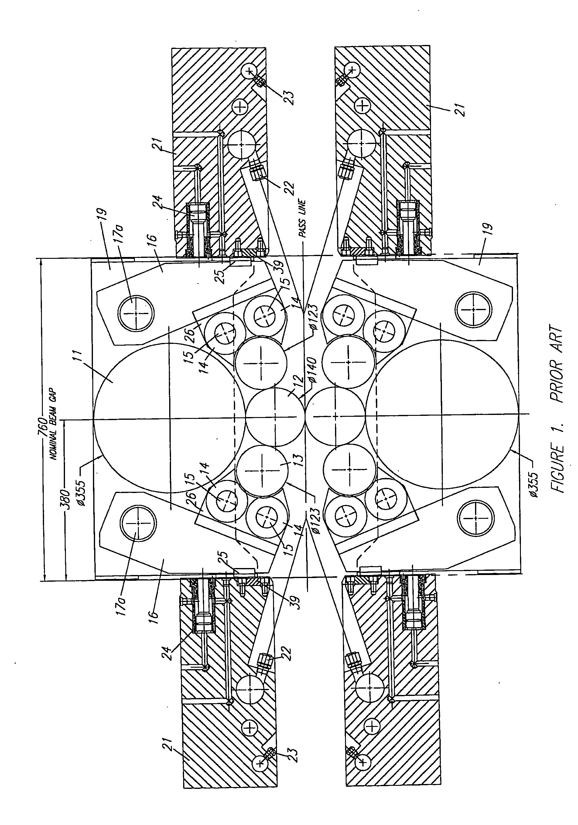
  • Side supported 6-high rolling mill
  • Side supported 6-high rolling mill
  • Side supported 6-high rolling mill

Examples


Embodiment Construction

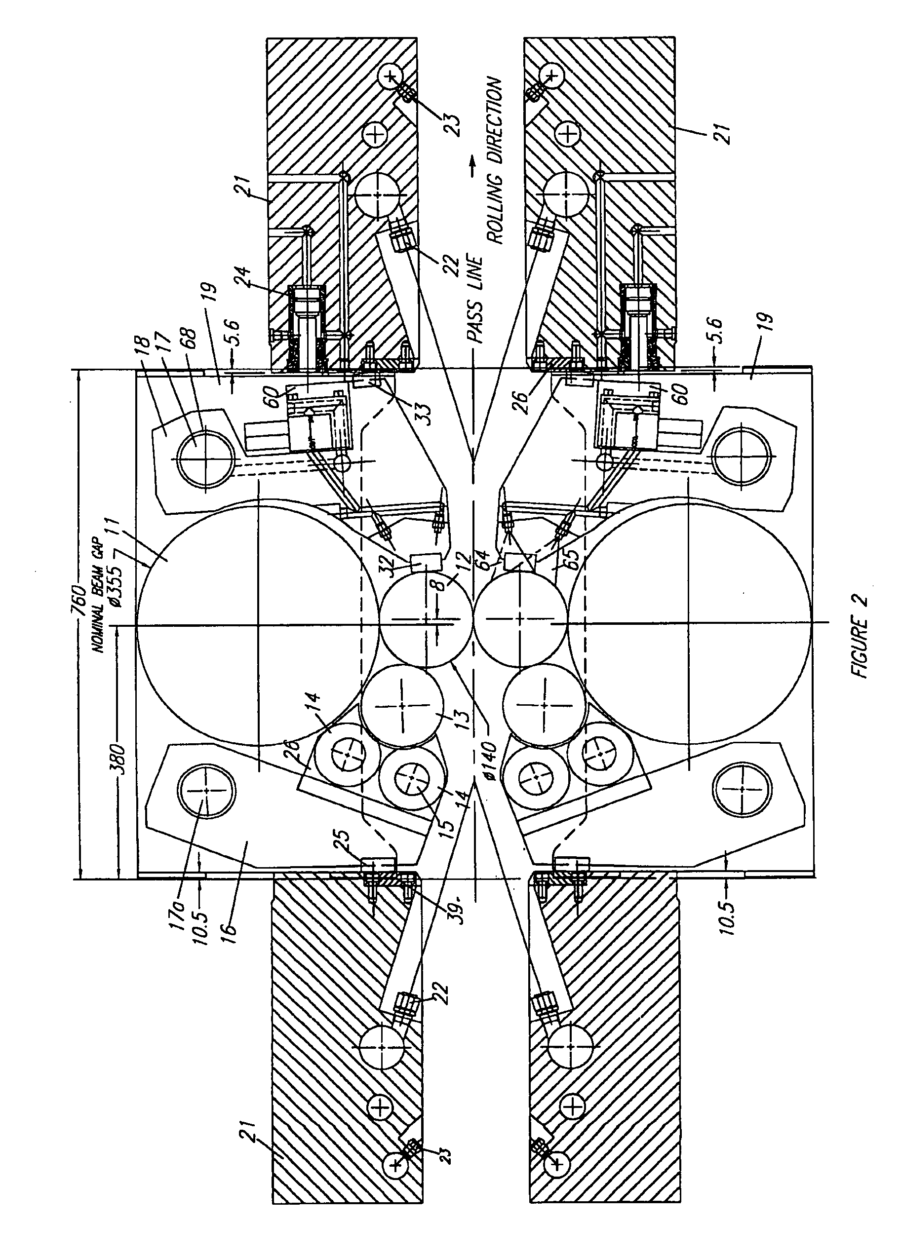
[0020] In the following description of an exemplary embodiment of the present invention, like numerals indicate like objects throughout the drawings. In the drawings, only work rolls, intermediate rolls and side support structures are shown. The back-up rolls and back-up roll chocks, mill housings and other mill structures are according to the prior art.

[0021] The prior art side supported 6-high mill shown in FIG. 1 includes intermediate rolls 11, bearing mounted in chocks 19, free floating work rolls 12, each work roll being supported at each side by side support roll 13, itself supported by caster bearings 14 mounted on shafts 15 supported by saddles 26 mounted on cluster arm 16. Each cluster arm 16 is mounted on shaft 17a, which extends between operator side and drive side intermediate roll chocks 19 and is pivot mounted between the chocks. Any horizontal force transmitted to cluster arm 16 passes through spacer bar 25 to liner 39 attached to side support beam 21 which is adjust...


PUM

PropertyMeasurementUnit
roll sizesaaaaaaaaaa
diameteraaaaaaaaaa

Abstract

A 6-high rolling mill has work rolls which have offsets, relative to the intermediate rolls, such that during operation there is a net horizontal force acting to urge the work rolls into engagement with the support rolls whereby substantially all horizontal support of the work rolls is provided by the support rolls. Support pads are located proximal the rolls' side faces, without exerting any substantial force on the work rolls during operation.

Description

TECHNICAL FIELD [0001] The invention relates to a 6-high cold rolling mill and more particularly to a non-reversing mill, rolling metal strip in a fixed direction through the mill. BACKGROUND ART [0002] The invention relates to a 6-high cold rolling mills having side supported work rolls of the kind described generally in U.S. Pat. Nos. 4,270,370 and 4,531,394. The improvements described herein are of particular use when the rolling mill is part of a continuous line described generally in U.S. Pat. No. 5,197,179 or is of the kind described in U.S. Pat. No. 6,041,036 or when the mill is supplied as a tandem mill, incorporating several mill stands rolling metal strip in a fixed direction. [0003] It is well known in the art that during rolling, drive torque must be delivered to the work rolls. Since the work rolls in such mills are free floating and thus are not driven, the torque must be delivered in the form of a tangential force which acts in a horizontal direction at the contact li...

Claims


Application Information

Patent Timeline
Patent Type & Authority Applications(United States)
IPC IPC(8): B21B13/14
CPCB21B13/145B21B2013/028B21B27/10B21B13/147
Inventor TURLEY, JOHN W.
Owner T SENDERCHIMO
Learn More