
Probe with embedded heater for nanoscale analysis

a nano-scale, heater-based technology, applied in heat measurement, mechanical roughness/irregularity measurement, instruments, etc., can solve the problems of limited sharpness, large hampered general acceptance of this technique, and high localized surface effects

Active Publication Date: 2006-11-16
BRUKER NANO INC
View PDF15 Cites 38 Cited by
  • Summary
  • Abstract
  • Description
  • Claims
  • Application Information

AI Technical Summary

Benefits of technology

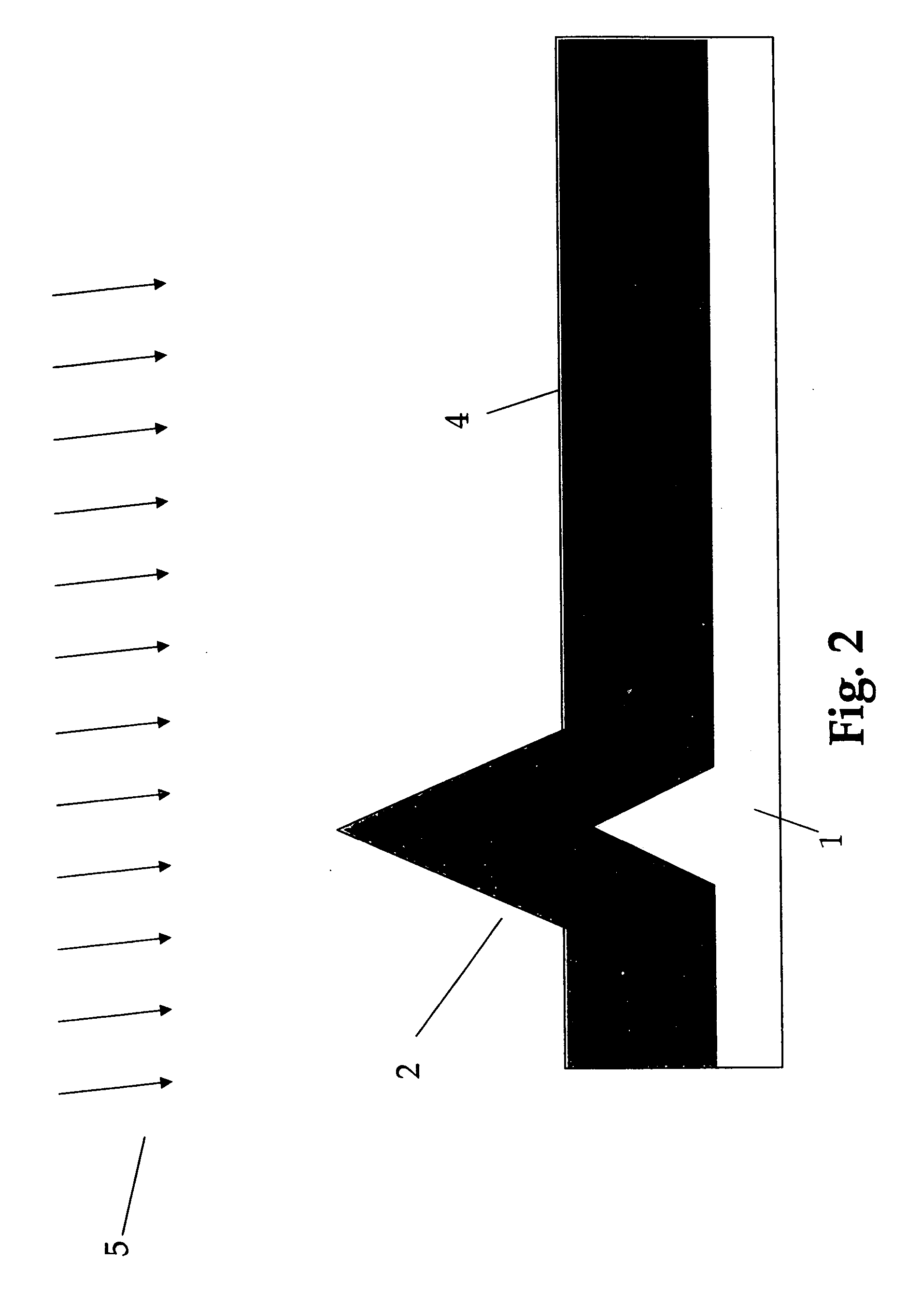
The invention is a microfabricated thermal probe that includes a planar cantilever with a probe tip, separate electrically conductive traces, and a heating element. The key design feature is that there is no spatial overlap between the base of the probe tip and the active area of the heating element. The probe tip is typically a single lever arm or formed from two lever arms joined by a cross piece between the arms near the free end. The length of the probe tip is preferably between 3 to 15 microns, and the heating element is preferably between 50% and 90% of the total electrical resistance of the trace-heating-element circuit. The invention allows for precise temperature control in microdevices and sensors.

Problems solved by technology

The heated probe will cause highly localized surface effects due to temperature.
The general acceptance of this technique has been greatly hampered by the commercially available thermal probes having a tip diameter in the order of 3 microns which restricts the spatial resolution to this regime.
Currently available Micro-TA probes are typically fabricated from fine wire, and the sharpness that can be achieved is limited.
This approach does not allow for suitably high temperatures.
If there are any defects in the film or any contact of the film to any other conductive surface the heating element can fail even at low temperatures and at higher temperatures the element will likely fail due to alloying, electro-migration, melting, or other failure mechanisms.
Such a short tip is suitable for some applications, but in general, use of such a short tip constrains the probe to interrogating surfaces with topography having roughness less that the length of the tip, thus unduly limiting the application of the technique.

Method used


Image

  • Probe with embedded heater for nanoscale analysis
  • Probe with embedded heater for nanoscale analysis
  • Probe with embedded heater for nanoscale analysis

Examples


Embodiment Construction

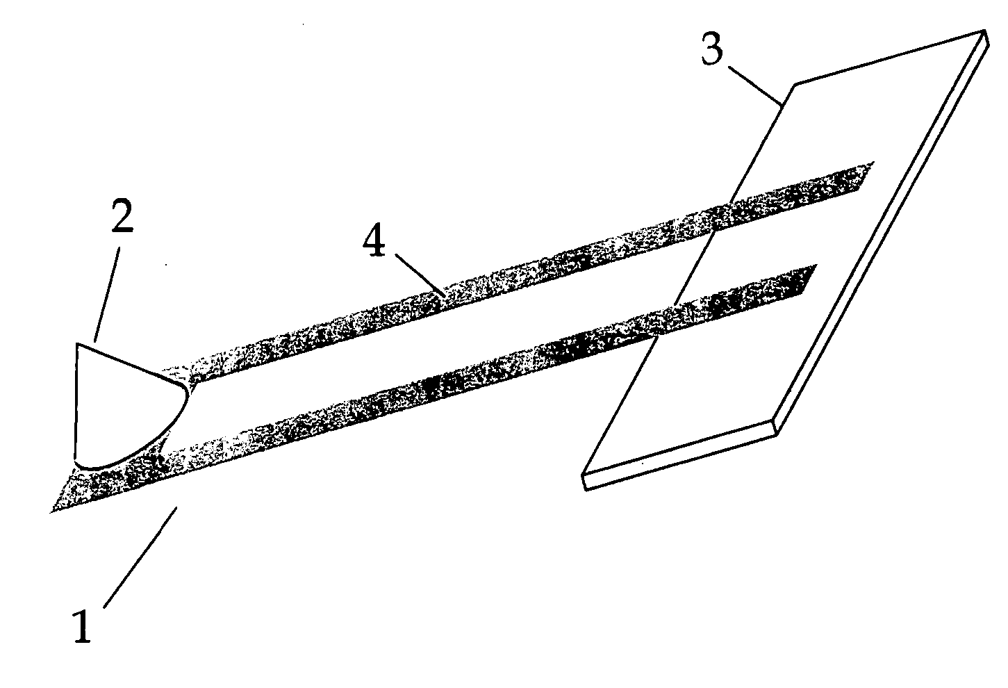
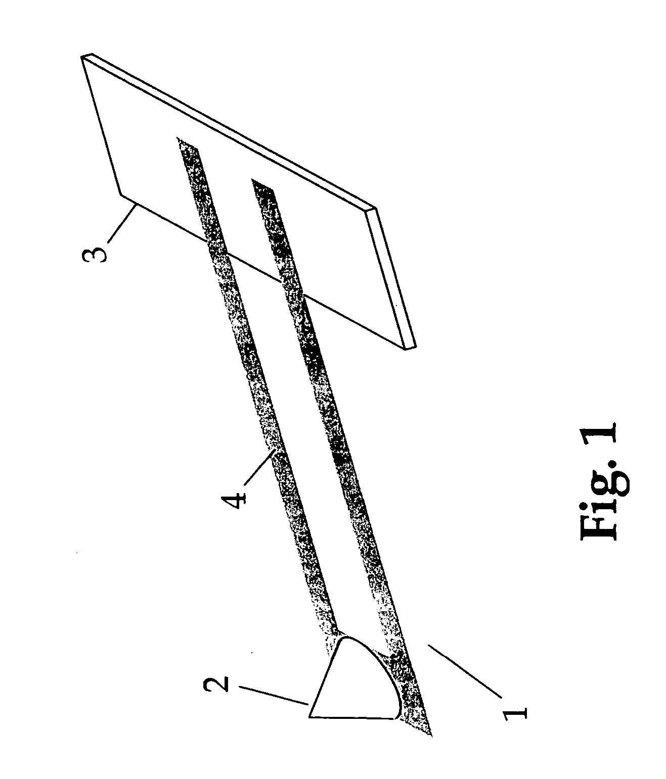
[0021]FIG. 1 shows schematically a cantilever probe with an integral resistive heater. The figure and all of the remaining figures are drawn to illustrate various features of the invention. It is to be understood that the figures are not to scale, particularly the dimensions of the probe tip, which are in fact less than 10% typically of the cantilever length-width dimensions, so drawing the tip to scale would diminish the illustrative value of the drawings. The novel lever is suitable for use as the probe in many varieties of SPM.

[0022] In FIG. 1, cantilever 4, in this case consisting of two parallel arms with a cross piece at the free end, extends from substrate 3. Probe tip 2 extends out of the plane of the lever and is typically situated near the free end of the lever. Although two parallel arms with a cross piece is the configuration shown in the drawings, other configurations are also possible and known, such as triangular levers, both one piece or two arms, and one-piece soli...


PUM


Abstract

The invention is a heated thermal probe suitable for use in micro- thermal analysis or other high resolution thermal measurements and actions. The probe is, in the preferred embodiment, a microfabricated cantilever with a sharp probe tip of a type used in Scanning Probe Microscopes (SPM's) which further includes an integral resistive heating element. The heating element is formed by doping regions of the cantilever with an ion implant process to make lower resistance connections and a higher resistance heating element. There is no spatial overlap between the base of the probe tip and the heating element or conductors.

Description

RELATED APPLICATIONS [0001] This application claims priority to U.S. provisional application, Ser. No. 60 / 672,270, filed Apr. 18, 2005FEDERALLY SPONSORED RESEARCH [0002] Not Applicable SEQUENCE LISTING [0003] Not Applicable BACKGROUND OF THE INVENTION [0004] This invention relates to probes for high resolution thermal analysis, and in particular a cantilever probe with an integral heating element. [0005] The family of thermal analysis techniques, collectively called micro-thermal analysis (micro-TA), has been in existence for nearly a decade now. Micro-TA methods are based on a scanning probe microscope in which the conventional passive probe, typically a cantilever arm with integral tip, is enhanced to measure temperature and be resistively heated. This type of scanning probe microscopy (SPM) is called scanning thermal microscopy (SThM, specifically in this application, SThM in which the probe is actively heated rather than the sample). This form of microscopy allows thermal proper...

Claims


Application Information

Patent Timeline
Patent Type & Authority Applications(United States)
IPC IPC(8): G01B5/28
CPCB82Y35/00G01Q70/14G01Q70/10G01Q60/58
Inventor KING, WILLIAM P.READING, MIKE
Owner BRUKER NANO INC
Learn More