Image displaying apparatus

a technology of scanning type and displaying apparatus, which is applied in the direction of static indicating devices, optical radiation measurement, instruments, etc., can solve the problems of increasing the number of parts, no specific configurations have been disclosed regarding a method for controlling output from each light source, and no disclosure regarding the ratio of output from a plurality of light sources. , to achieve the effect of favorable image quality

Inactive Publication Date: 2006-11-16
CANON KK
View PDF9 Cites 78 Cited by
  • Summary
  • Abstract
  • Description
  • Claims
  • Application Information

AI Technical Summary

Benefits of technology

[0036] According to the present invention, an image displaying apparatus capable of displaying a color image with favorable image quality on a predetermined surface can be obtained.

Problems solved by technology

However, no specific configurations have been disclosed regarding a method for controlling output from each light source means.
However, there have been no disclosures regarding a ratio of output from a plurality of light source means when a plurality of light source means are used to display color images.
However, this leads to an increase in the number of parts, which in turn makes the entire apparatus more complicated.

Method used


Image

  • Image displaying apparatus
  • Image displaying apparatus
  • Image displaying apparatus

Examples


first embodiment

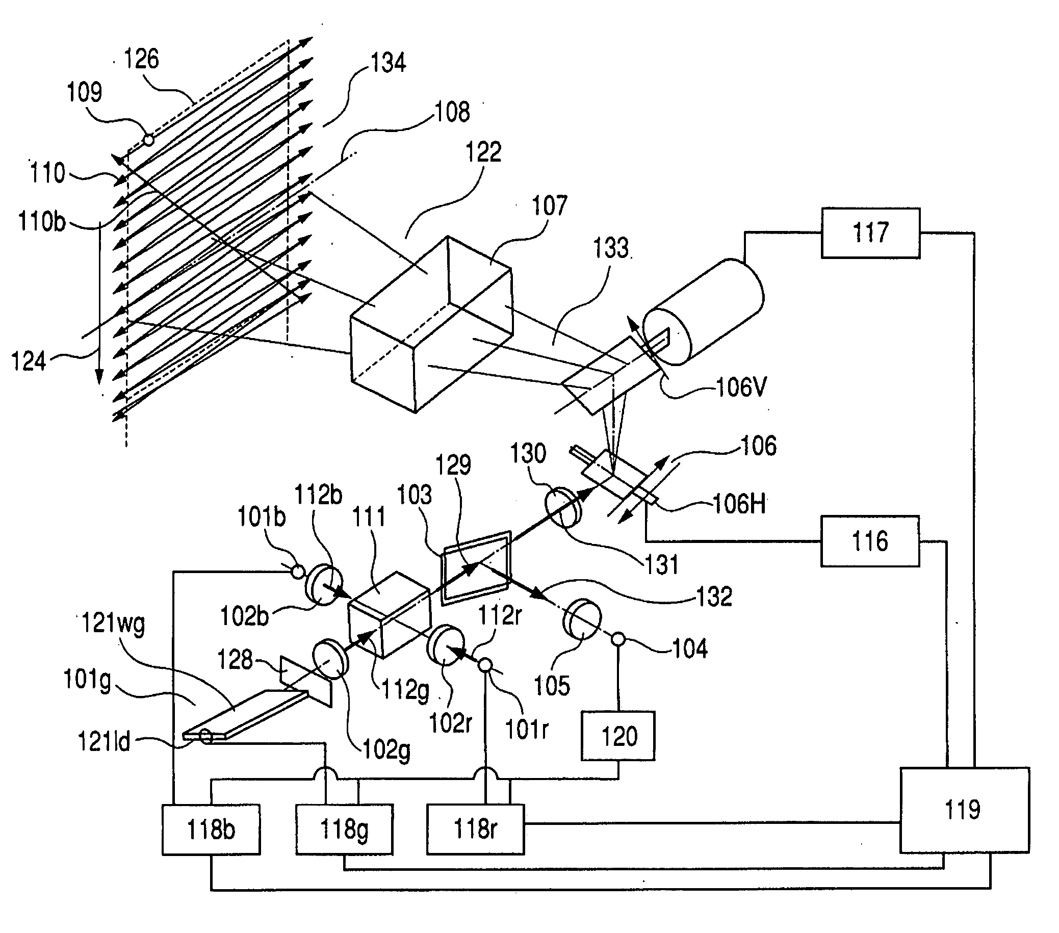
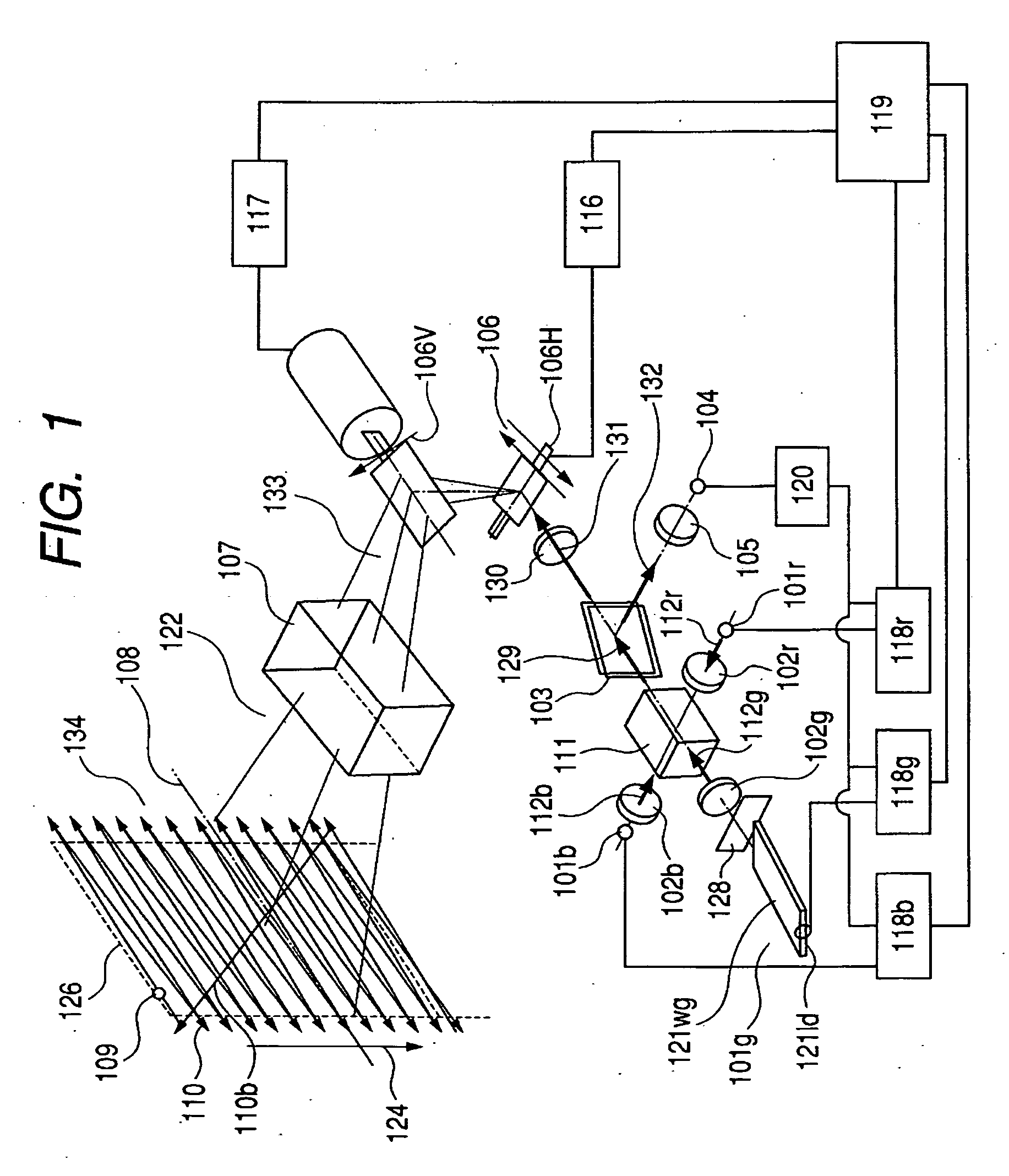
[0053]FIG. 1 is a block diagram of a configuration of a light-scanning-type image displaying apparatus according to the present invention. In FIG. 1, reference characters 101r, 101g and 101b respectively denote light sources (light source means) that emit red, green and blue light, respectively.

[0054] The light sources 101r and 101b are semiconductor lasers. The light source 101g is a two-dimensional higher harmonic wave laser light source composed of an infrared laser 121ld and a wavelength conversion element 121wg.

[0055] The infrared laser 121ld emits infrared coherent light having a wavelength in the vicinity of 1060 nm, while the wavelength conversion element 121wg converts the infrared light to a light beam having a wavelength of 530 nm or half of the 1060 nm. Reference numeral 128 denotes an infrared cut filter that blocks infrared light.

[0056] Optical systems 102r, 102g and 102b respectively alter (convert into light beams) the light emitted from the light sources 101r, 10...

second embodiment

[0093] A second embodiment of the present invention will now be described.

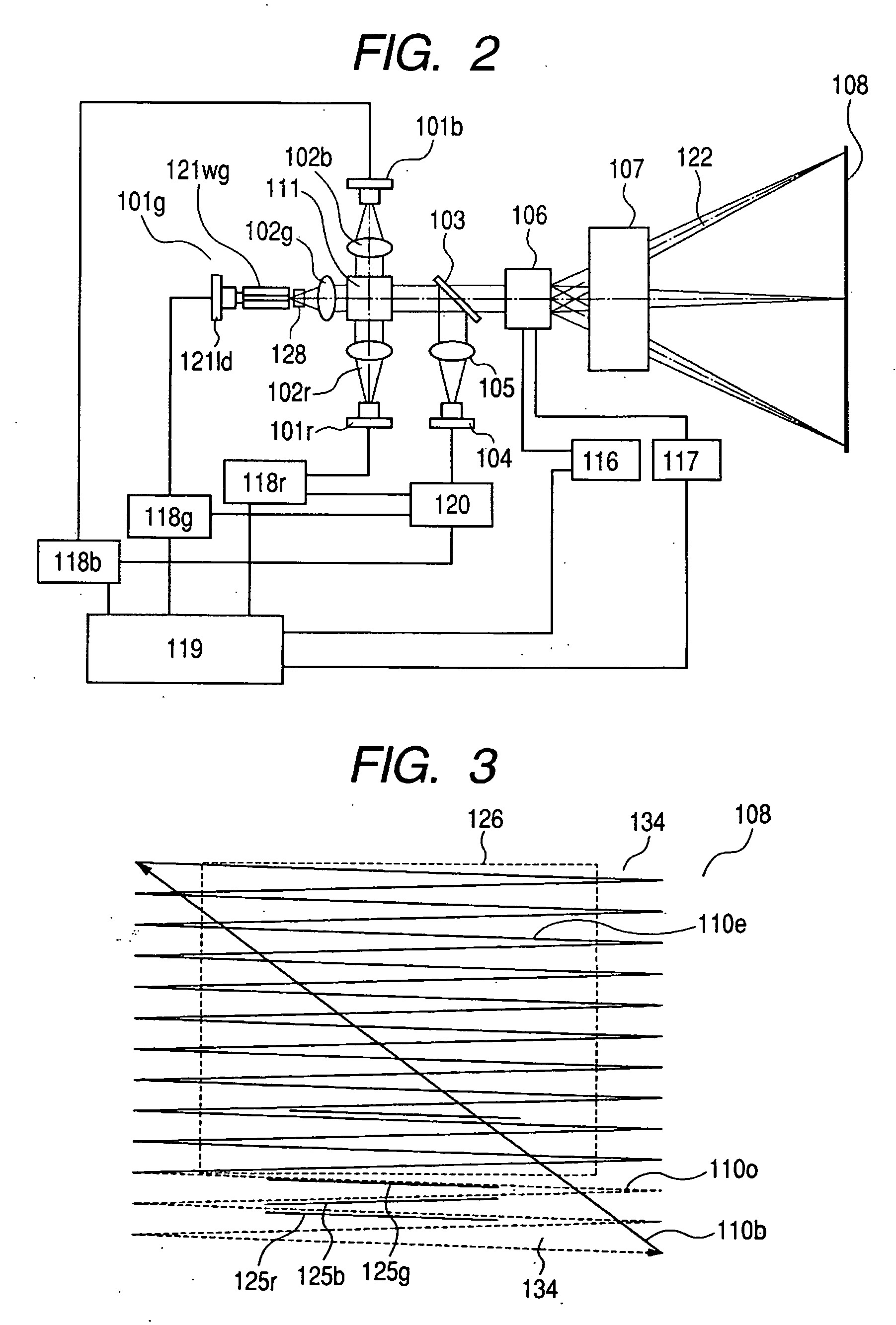
[0094]FIG. 9 is a schematic block diagram of a light-scanning-type image displaying apparatus of the present invention that has been simplified in the same manner as in FIG. 2.

[0095] In FIG. 9, light sources 201r, 201g and 201b are laser light sources that respectively emit red, green and blue light.

[0096] The light sources 201r and 201b are semiconductor lasers. The semiconductor laser 201b is configured to have a built-in package consisting of a laser light source 201b_LD and a light receiving element 201b_pd for monitoring light quantities.

[0097] The light source 101g is a two-dimensional higher harmonic wave laser light source composed of an infrared laser 209ld and a wavelength conversion element 209wg. The infrared laser 209ld emits infrared light having a wavelength in the vicinity of 1060 nm, while the wavelength conversion element 209wg converts the infrared light to a light beam having a waveleng...

third embodiment

[0119] A third embodiment of the present invention will now be described.

[0120]FIG. 12 is a schematic block diagram of a light-scanning-type image displaying apparatus of the present invention that has been simplified in the same way as in FIG. 2.

[0121] In FIG. 12, light sources 301r, 301g and 301b are laser light sources that respectively emit red, green and blue light.

[0122] The light sources 301r and 301b are semiconductor lasers. The light source 301g is a two-dimensional higher harmonic wave laser light source composed of an infrared laser 309ld and a wavelength conversion element 309wg.

[0123] The infrared laser 309ld emits infrared light having a wavelength of in the vicinity of 1060 nm, while the wavelength conversion element 309wg converts the infrared light to a light beam having a wavelength of 530 nm, or half of the 1060 nm wavelength. Reference numeral 310 denotes an infrared cut filter that blocks infrared laser light.

[0124] The optical systems 302r, 302g and 302b ...


PUM


Abstract

An image displaying apparatus displaying a color image with favorable quality on a predetermined surface comprises; light source unit for emitting light beams within different wavelength ranges optically modulated by image information; light combining unit for combining light beams from the light source unit into a light beam; scanning unit for scanning a scanned surface with the light beam from the light combining unit and forming image thereon; and controlling unit for synchronously controlling the scanning unit and the light source unit, wherein dividing unit for dividing a light beam into light beams is provided within an arbitrary optical path on light-incident side of the scanning unit; receiving unit and adjustment unit for adjusting quantity of light emission of one or more light source unit based on the light quantity received by the receiving unit are provided on one of the optical paths divided by the dividing unit.

Description

BACKGROUND OF THE INVENTION [0001] 1. Field of the Invention [0002] The present invention relates to a scanning-type image displaying apparatus for displaying images on a predetermined surface by scanning the predetermined surface with light beams which are modulated based on image information and are emitted from light source means, using scanning means. [0003] 2. Related Background Art [0004] Conventionally, liquid crystal projectors or DLP projectors, in which a two-dimensional spatial modulator such as a liquid crystal element is illuminated with light beams from light source means such as a halogen lamp using an illuminating optical system, and light beams from the two-dimensional spatial modulator are projected onto a screen to be observed using a projection lens, are known as projection-type image displaying apparatuses. [0005] In contrast, scanning-type image displaying apparatuses, in which a screen is scanned with laser light modulated based on image information using scan...

Claims


Application Information

Patent Timeline
Patent Type & Authority Applications(United States)
IPC IPC(8): H01L27/00
CPCG02B26/101G02B27/102G02B27/104G02B27/108G02B27/1086H04N9/3129G02B27/145G03B21/28G03B33/12G09G3/02G02B27/141
Inventor KOBAYASHI, SHUICHIISHIHARA, KEIICHIROSOEDA, YASUHIRO
Owner CANON KK
Why Eureka
Try Eureka